Vehicle pedal device

A technology for pedaling and automobiles, which is applied in the field of auto parts, and can solve the problems of large space and difficulty of the welcome pedal, and the distance between the door and the ground, etc., and achieve the effect of compact structure, reduced space and improved service life

Active Publication Date: 2015-02-04
JIAXING VOCATIONAL TECHN COLLEGE
View PDF4 Cites 0 Cited by
  • Summary
  • Abstract
  • Description
  • Claims
  • Application Information

AI Technical Summary

Problems solved by technology

[0002] Due to the large distance between the door and the ground of existing SUV cars, it is more difficult for short people to directly enter the body through the door.
Therefore, most existing SUV cars are provided with welcome pedals, but these welcome p

Method used


Image

  • Vehicle pedal device
  • Vehicle pedal device
  • Vehicle pedal device

Examples


Embodiment 1

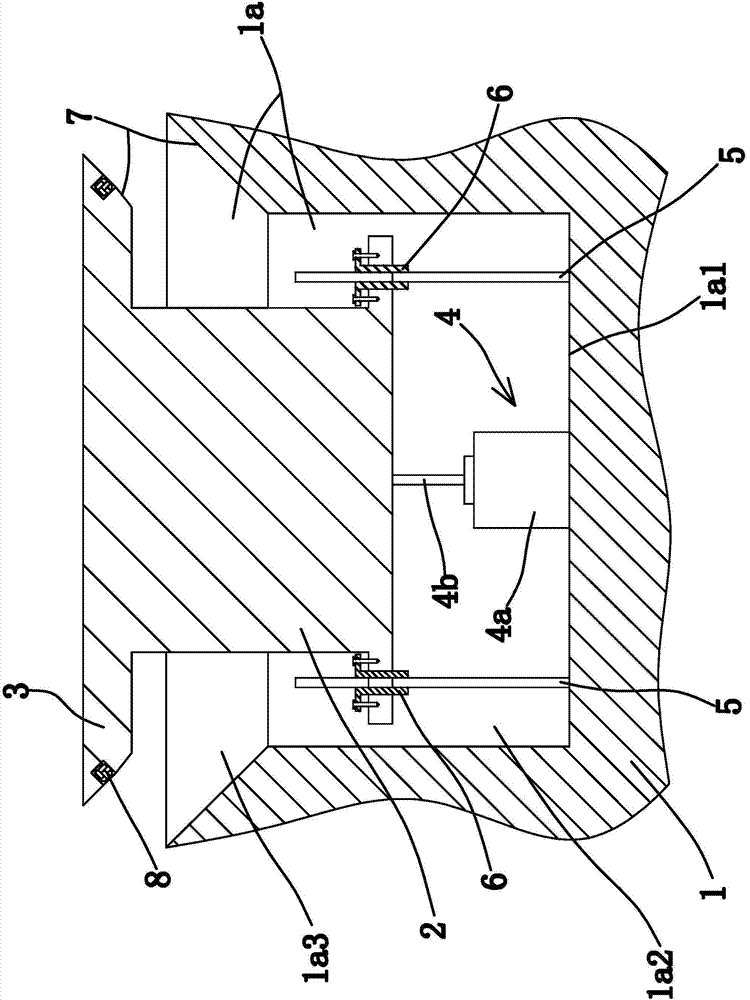
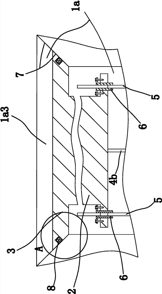
[0049] Such as figure 1 As shown, the automobile stepping device includes a body body 1, a driving member, a pedal 2, a sealing plate 3 and the like. Among them, in an existing automobile, two opposite side walls of the body body 1 are connected with doors for people to enter the body.

[0050] Specifically, the two side walls connected to the vehicle door on the body body 1 are provided with grooves 1a. Both grooves 1a include a flat bottom wall 1a1 and a cylindrical inner side wall.

[0051] Both the pedal 2 and the driving member are located in the groove 1a, and the driving member can drive the outer end of the pedal 2 to extend out of the groove 1a for people to step on. In this embodiment, the driving part is a cylinder 4, which includes a cylinder block 4a and a cylinder piston rod 4b. The cylinder block 4a is fixedly connected to the bottom wall 1a1 by welding, so that the cylinder 4 is stably connected to the bottom wall. 1a1 phase solid connection.

[0052] The pedal 2 is...

Embodiment 2

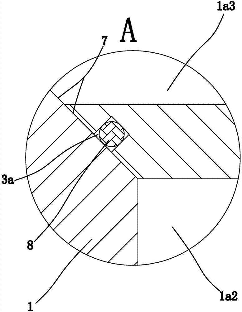
[0063] The structure and principle of the second embodiment are basically the same as those of the first embodiment. The difference is that the guide assembly 7 includes the outer side wall of the sealing plate 3, the outer side wall of the sealing plate 3 is tapered and the diameter of the outer side wall of the sealing plate 3 is concave. The inside of the groove 1a gradually decreases. When the sealing plate 3 slides out, the tapered outer side wall of the sealing plate 3 is provided to guide the sealing plate 3 so that the sealing plate 3 can smoothly open the groove 1a, thereby reducing the time for the pedal 2 to slide out , So that the pedal 2 can slide out very smoothly; when the sealing plate 3 is retracted, the tapered outer side wall of the sealing plate 3 is provided to guide the sealing plate 3, so that the sealing plate 3 can always be retracted to the same Position and seal the groove 1a, so that when the sealing plate 3 abuts against the abutting portion 1a3, th...

Embodiment 3

[0065] The structure and principle of the third embodiment is basically the same as that of the first embodiment. The difference is that the guide assembly 7 includes the inner side wall of the abutting portion 1a3, the inner side wall of the abutting portion 1a3 is tapered, and the inner side wall of the abutting portion 1a3 The diameter gradually decreases toward the inner side of the connecting portion 1a2. When the sealing plate 3 slides out, the tapered inner wall of the abutting portion 1a3 is provided to guide the sealing plate 3, so that the sealing plate 3 can smoothly open the groove 1a, thereby reducing the sliding of the pedal 2 Time, the pedal 2 can slide out very smoothly; when the sealing plate 3 is retracted, the inner side wall of the abutting portion 1a3 is provided to guide the sealing plate 3 so that the sealing plate 3 can always be retracted To the same position and seal the groove 1a, so that when the sealing plate 3 abuts against the abutting portion 1a3...


PUM


Abstract

The invention provides a vehicle pedal device and belongs to the technical field of vehicle fittings. The problem of relatively large occupation space caused when the current welcoming pedal cannot be retracted when not being used is solved. The vehicle pedal device comprises a vehicle body, wherein vehicle doors are connected to two opposite side walls on the vehicle body; grooves are formed in the two side walls, connected with the vehicle doors, of the vehicle body; each groove comprises a planar bottom wall; a pedal and a plurality of guide components which are vertically arranged on the bottom wall are arranged in each groove; the pedals are long bar-shaped and are glidingly connected to the guide components; a driving component enabling the outer end of each pedal to go out of the groove is also arranged in each groove; a sealing plate which can seal each groove is connected with the outer end of each pedal. The vehicle pedal device has the advantage of retracting the pedals.

Description

Technical field [0001] The invention belongs to the technical field of automobile parts, and relates to an automobile stepping device. Background technique [0002] Due to the large distance between the door and the ground of the existing SUV, it is difficult for people with shorter height to enter the vehicle body directly through the door. Therefore, most of the existing SUV cars are equipped with welcome pedals, but most of these welcome pedals are directly fixed on the outer side wall of the body, but when the welcome pedal is not used, the existing SUV cars do not have a characteristic structure. The welcome pedal retracts, causing the welcome pedal to take up more space. Summary of the invention [0003] The purpose of the present invention is to solve the above-mentioned problems in the prior art, and to propose an automobile pedal device that can be retracted when the pedal is not in use. [0004] The object of the present invention can be achieved by the following technic...

Claims


Application Information

Patent Timeline
IPC IPC(8): B60R3/02B62D25/22
CPCB60R3/02
Inventor 吕灵巧
Owner JIAXING VOCATIONAL TECHN COLLEGE
Why Eureka
Try Eureka