Granular Cotton Preparation System

A preparation system and technology of granular cotton, applied in glass manufacturing equipment, manufacturing tools and other directions, to achieve the effect of improving fiber formation rate and quality, and promoting the formation of vitrification

Inactive Publication Date: 2016-09-07
宝钢矿棉科技(宁波)有限公司
View PDF4 Cites 0 Cited by
  • Summary
  • Abstract
  • Description
  • Claims
  • Application Information

AI Technical Summary

Problems solved by technology

The outer surface of the centrifugal roll of this application is smooth arc surface equally, and it also has above-mentioned deficiency

Method used


Image

  • Granular Cotton Preparation System
  • Granular Cotton Preparation System
  • Granular Cotton Preparation System

Examples


Embodiment 1

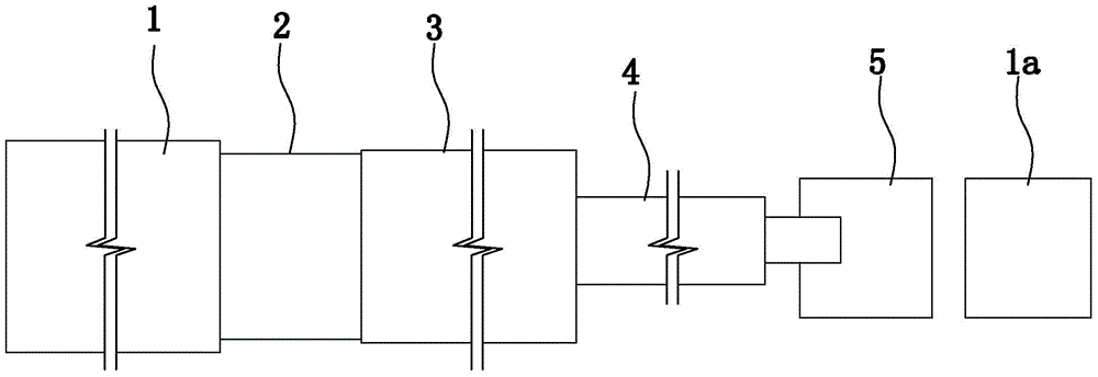
[0050] Embodiment 1: as figure 1 As shown, a granular cotton preparation system includes a slag furnace, a four-roller centrifuge 5, a cotton collector and a granulator; the cotton collector and granulator in this embodiment are prior art.

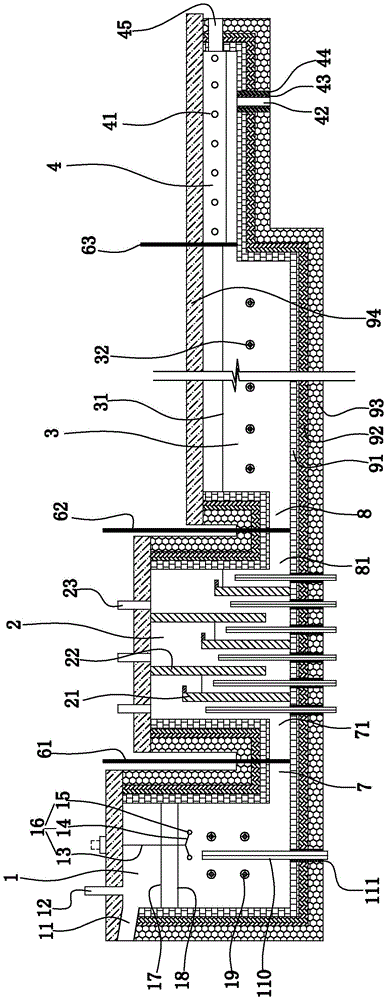
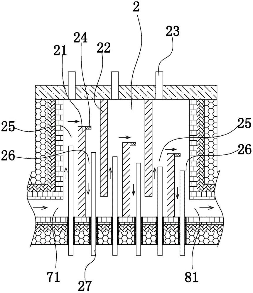
[0051] Such as figure 1 , such as 2, image 3 , Figure 4 As shown, the slag furnace includes a feeding pool 1, a homogenizing pool 2, a melting pool 3 and a forehearth 4 in sequence. The upper part of the feeding pool is provided with a slag inflow port 11 and a main conditioning material feeding port 12 . The bottom of the feeding tank and the bottom of the homogenizing tank are connected through a first flow channel 7 . The bottom of the homogenizing tank and the bottom of the melting tank are connected through the second flow channel 8 . One end of the forehearth communicates with the melting pool, and the other end is closed. The lower part of the material channel is provided with a material outlet. The bottom of the feeding ta...

Embodiment 2

[0072] Embodiment 2: all the other structures in this embodiment are with reference to embodiment 1, and its difference is:

[0073] Such as figure 1 , Figure 8 As shown, the cotton collector 1a includes a cotton collector shell, a cotton mesh belt device, a cotton inlet air port 5a and a negative pressure air port 15a on the cotton collector shell, a cotton conveyor belt 8a and a cotton conveyor belt positioned outside the cotton collector shell. Scraper 7a. The cotton outlet air outlet of the centrifuge is set opposite to the cotton inlet air outlet of the cotton collector, and the distance between the cotton outlet air outlet and the cotton inlet air outlet is between 1 and 1.6 meters. An exhaust fan is provided at the negative pressure air outlet of the cotton collector.

[0074] A cotton collecting chamber 2a, an air-drying chamber 3a and a cleaning chamber 4a are sequentially arranged in the cotton collecting machine shell. The cotton-collecting mesh belt device com...


PUM

PropertyMeasurementUnit
distanceaaaaaaaaaa
angleaaaaaaaaaa

Abstract

The invention discloses a granular wool manufacturing system and aims to provide the granular wool manufacturing system which not only can fully utilize residual heat resources in blast furnace thermal-state slag and is energy-saving and environmental-protective but also can enable a melt in a slag furnace to be melted uniformly, a vitrification degree to be high and a fiber-forming ratio and quality of mineral wool to be improved. The device includes a slag furnace, a four-roller centrifugal machine and a wool-collecting machine. The slag furnace successively includes a feeding tank, a homogenizing tank, a melting tank and a material path. A slag flow inlet and a main modulating material feeding port are arranged on an upper part of the feeding tank. The bottom of the feeding tank is connected to the bottom of the homogenizing tank through a first liquid flowing path. The bottom of the homogenizing tank is communicated with the bottom of the melting tank through a second liquid flowing path. One end of the material path is communicated with the melting tank and the other end of the material path is closed. In addition, a material outlet port is arranged at the bottom of the material path. The four-roller centrifugal machine includes a centrifugal machine shell and four centrifugal rollers arranged inside the centrifugal machine shell, wherein external surfaces of the centrifugal rollers are respectively provided with spiral grooves surrounding the centrifugal rollers.

Description

technical field [0001] The invention relates to the field of mineral wool production, in particular to a granular cotton preparation system. Background technique [0002] Mineral wool uses industrial waste slag (blast furnace slag, etc.) Under the action of the centrifugal force generated by the roller, it is thrown into mineral wool fibers; at the same time, the mineral wool fibers are blown into the cotton collector with the high-speed airflow ejected from the wind ring in the centrifuge (the high-speed airflow ejected from the air ring is on the centrifugal roller shaft. Upward, high speed flow along the surface of the centrifugal roller). The mineral wool fiber in the cotton collector gathers on the mesh belt of the cotton collector under the action of negative pressure wind suction to form a mineral wool felt. Mineral wool has the characteristics of light weight, small thermal conductivity, non-combustible, moth-proof, cheap, corrosion-resistant, good chemical stabili...

Claims


Application Information

Patent Timeline
Patent Type & Authority Patents(China)
IPC IPC(8): C03B37/005
CPCC03B37/005
Inventor 沈健陈铁军王品益朱春江李胜春高晓骏
Owner 宝钢矿棉科技(宁波)有限公司
Why Eureka
Try Eureka