
Granular wool manufacturing system
A preparation system and granular cotton technology, applied in the direction of glass manufacturing equipment, manufacturing tools, etc., to achieve the effect of improving the fiber formation rate and quality, and promoting the formation of vitrification
- Summary
- Abstract
- Description
- Claims
- Application Information
AI Technical Summary
Problems solved by technology
Method used
Image

Examples
Embodiment 1
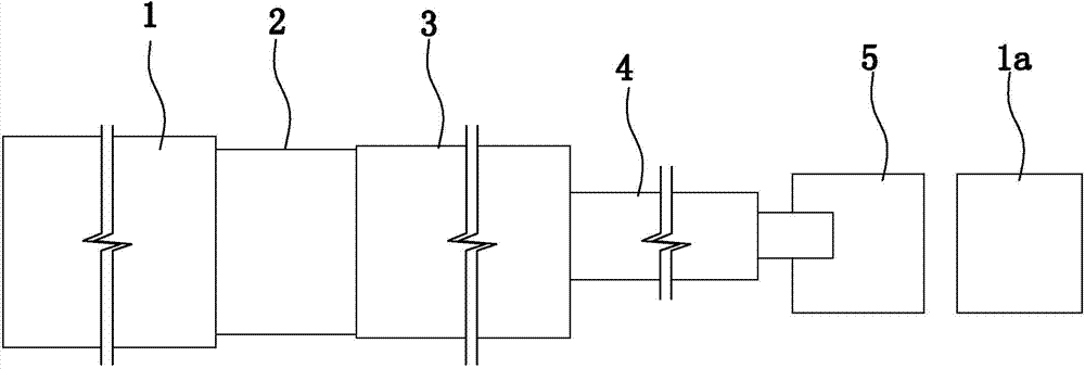
[0050] Embodiment 1: as figure 1 As shown, a granular cotton preparation system includes a slag furnace, a four-roller centrifuge 5, a cotton collector and a granulator; the cotton collector and granulator in this embodiment are prior art.
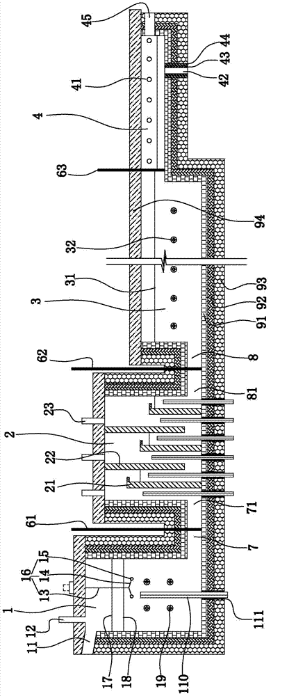
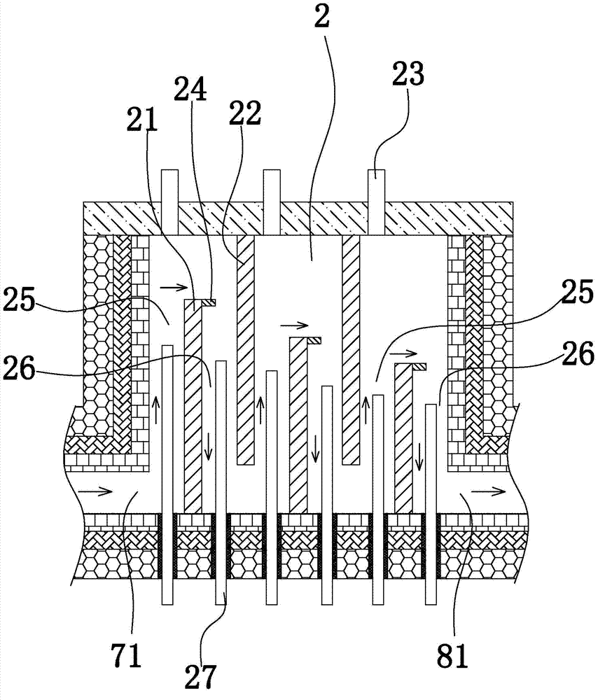
[0051] Such as figure 1 , such as 2, image 3 , Figure 4 As shown, the slag furnace includes a feeding pool 1, a homogenizing pool 2, a melting pool 3 and a forehearth 4 in sequence. The upper part of the feeding pool is provided with a slag inflow port 11 and a main conditioning material feeding port 12 . The bottom of the feeding tank and the bottom of the homogenizing tank are connected through a first flow channel 7 . The bottom of the homogenizing tank and the bottom of the melting tank are connected through the second flow channel 8 . One end of the forehearth communicates with the melting pool, and the other end is closed. The lower part of the material channel is provided with a material outlet. The bottom of the feeding ta...
Embodiment 2
[0072] Embodiment 2: all the other structures in this embodiment are with reference to embodiment 1, and its difference is:
[0073] Such as figure 1 , Figure 8 As shown, the cotton collector 1a includes a cotton collector shell, a cotton mesh belt device, a cotton inlet air port 5a and a negative pressure air port 15a on the cotton collector shell, a cotton conveyor belt 8a and a cotton conveyor belt positioned outside the cotton collector shell. Scraper 7a. The cotton outlet air outlet of the centrifuge is set opposite to the cotton inlet air outlet of the cotton collector, and the distance between the cotton outlet air outlet and the cotton inlet air outlet is between 1 and 1.6 meters. An exhaust fan is provided at the negative pressure air outlet of the cotton collector.
[0074] A cotton collecting chamber 2a, an air-drying chamber 3a and a cleaning chamber 4a are sequentially arranged in the cotton collecting machine shell. The cotton-collecting mesh belt device com...
PUM
| Property | Measurement | Unit |
|---|---|---|
| distance | aaaaa | aaaaa |
| angle | aaaaa | aaaaa |
Abstract
Description
Claims
Application Information