Novel precision-type high-pressure-resistant rotary compensator

A rotary compensator, a precise technology, applied to expansion compensation devices for pipelines, pipes/pipe joints/pipes, adjustable connections, etc. problems such as large investment and pressure loss, to achieve the effect of safe pipeline operation, small pressure loss and strong pressure bearing capacity

Inactive Publication Date: 2015-02-04
陈墅庚
View PDF8 Cites 9 Cited by
  • Summary
  • Abstract
  • Description
  • Claims
  • Application Information

AI Technical Summary

Problems solved by technology

[0003] The pipeline compensation method in the prior art mostly adopts the original natural compensation method, and the investment and pressure loss are relatively large; the structure and sealing performance of the compensator are not good, and the leakage phenomenon is serious; the performance of the rotary compensator is relatively good; Flexible, especially in long-distance overhead pipelines, the application advantages are obvious; but there are also shortcomings: First, the gap between the inner tube and the reducing tube is too large, and eddy currents will be generated at this part during the movement of the fluid medium, so increases the pressure loss of the fluid medium
Second, because the structure of the rotary compensator is a radial working principle, it must occupy a certain amount of extra space when it is applied in the pipeline; and each set of compensator installation points must be equipped with a steam trap; this increases the cost and pressure of the pipeline network. Moreover, it cannot be widely used in buried pipelines; most of the existing compensators adopt a single sealing form, and in use: fluid medium and pressure bearing capacity are all subject to certain limitations

Method used


Image

  • Novel precision-type high-pressure-resistant rotary compensator
  • Novel precision-type high-pressure-resistant rotary compensator

Examples


Embodiment Construction

[0048] The technical solution of the present invention will be described in detail below in conjunction with the accompanying drawings.

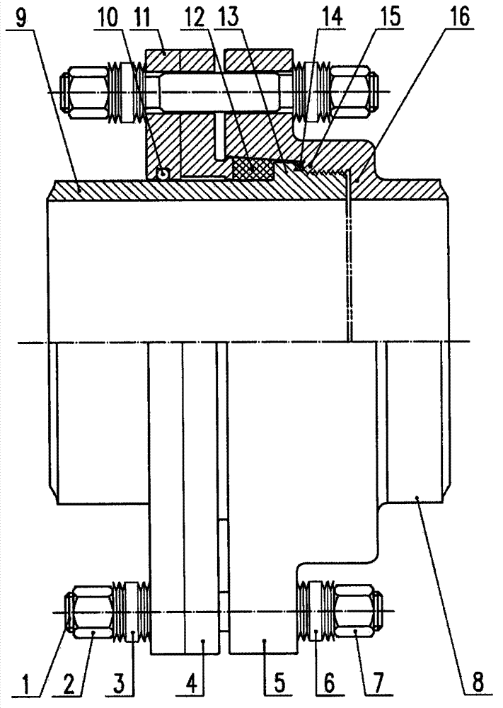
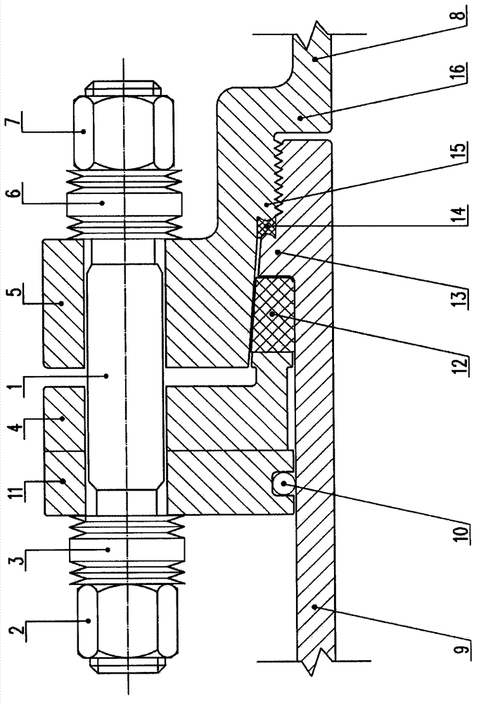
[0049] Such as figure 1 , figure 2 Shown; a new type of precision high-pressure rotary compensator, including: stud bolt 1, nut A2, disc spring A3, seal compression flange 4, reducer flange 5, disc spring B6, nut B7, Reducer tube 8, inner tube 9, steel ball 10, outer gland flange 11, graphite seal 12, inner tube convex outer ring 13, metal winding gasket 14, reducer inner cap B15 and reducer inner cap A16;

[0050] The internal diameter of the inner tube 9 is the same as that of the reducer tube 8, and the inner end is coaxially inserted; the detailed description is as follows: figure 1 As shown, that is, the inner tube 9 is a columnar tube structure, arranged horizontally, one end (or right end) is the inner end, and the other end (or left end) is the outer end; the reducing tube 8 is a columnar tube structure, arranged horizontally, O...


PUM


Abstract

The invention discloses a novel precision-type high-pressure-resistant rotary compensator and belongs to the technical field of heat power pipeline compensation device structures. The novel precision-type high-pressure-resistant rotary compensator comprises an outer pressing cover flange, a sealing piece pressing flange and a reducer pipe, wherein the outer pressing cover flange is integrated by fixing a stud, a nut A and a nut B; an inner pipe with an inner pipe convex outer ring is inserted into the reducer pipe and is spirally connected with the reducer pipe; a structure that the reducer pipe, the outer pressing cover flange, the sealing piece pressing flange and the inner pipe can coaxially, synchronously, entirely, relatively and rotatably move along the radial direction by virtue of the rotation of a threaded area when being pushed by radial heat expansion force is formed, and the reducer pipe, the outer pressing cover flange and the sealing piece pressing flange are fixed integrally. With the structure, the novel precision-type high-pressure-resistant rotary compensator has the advantages that the coaxial accurate is high, the pressure bearing capacity is higher, the flowing direction of a medium is not limited, and a pipeline is safer to operate and convenient to maintain.

Description

technical field [0001] The invention relates to a novel precision high-pressure-resistant rotary compensator, which belongs to the technical field of thermal pipeline compensation device structures, and specifically belongs to the technical field of thermal pipeline compensation device structures used in industries such as petroleum, chemical industry, light industry, thermal power, and metallurgy. . Background technique [0002] The compensator is also called the expansion joint or the expansion joint, and it is mainly used to compensate the thermal expansion and contraction of the pipeline caused by the temperature change. If the pipe is not completely free to expand or contract when the temperature changes, thermal stresses will develop in the pipe. Under the action of this stress in the pipeline, it may cause the rupture of the pipeline and affect the normal production. As an important part of pipeline engineering, compensators play an important role in ensuring the lo...

Claims


Application Information

Patent Timeline
Patent Type & Authority Applications(China)
IPC IPC(8): F16L51/00F16L27/08
CPCF16L51/00F16L27/08
Inventor 陈墅庚程广青马洪波夏孝刚陈振兴高轶
Owner 陈墅庚
Why Eureka
Try Eureka