Rasterization polar coordinate system target positioning method

A target positioning and polar coordinate system technology, applied in image data processing, instruments, camera devices, etc., can solve the problem that the photoelectric intelligent perception platform cannot accurately and quickly achieve target positioning, and achieve the effect of fast target positioning

Inactive Publication Date: 2015-02-04
ZHONGBEI UNIV
View PDF5 Cites 7 Cited by
  • Summary
  • Abstract
  • Description
  • Claims
  • Application Information

AI Technical Summary

Problems solved by technology

[0011] In order to solve the technical problem that the current photoelectric intelligent perception platform cannot accurately and quickly realize the target positioning, the present invention provides a gridded polar coordinate system target positioning method

Method used


Image

  • Rasterization polar coordinate system target positioning method
  • Rasterization polar coordinate system target positioning method
  • Rasterization polar coordinate system target positioning method

Examples


Embodiment Construction

[0044] The present invention will be further described in detail below in conjunction with the accompanying drawings and specific implementation.

[0045] (1) System structure composition

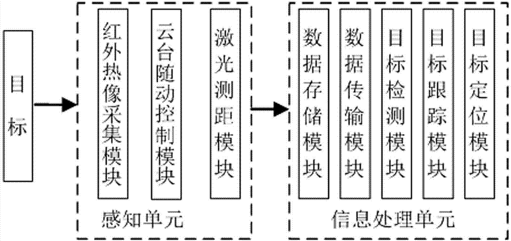
[0046] like figure 1 As shown, the present invention is mainly composed of two major units, that is, a perception unit and an information processing unit. The perception unit is mainly composed of infrared thermal image acquisition module, pan-tilt follow-up control module and laser ranging module; the information processing unit is mainly composed of data storage module, data transmission module, target detection module, target tracking module and target positioning module. Among them, in the sensing unit, the infrared thermal image acquisition module is mainly used to collect target images; the pan-tilt follow-up control module is used to control the rotation and pitch of the thermal imager. In the information processing unit, the data storage module is used to cache the frame-by-frame...


PUM


Abstract

The invention relates to a visual positioning method, belongs to the technical field of computer image processing, and in particular relates to a rasterization polar coordinate system target positioning method. The rasterization polar coordinate system target positioning method comprises the following steps: (a) calibrating a camera; (b) constructing a positioning model; (c) detecting a dynamic target; (d) determining a mass center of a target; (e) matching a mass center point; and (f) calculating a direction and a distance, namely calculating a distance p between a point O and the mass center point P according to a concentric circle determined by mass center point matching and calculating a position coordinate (p, theta) of the target point according to a position obtained by rotation of a cloud and an included angle theta of the axis OX. The rasterization polar coordinate system positioning method is added on a photoelectric comprehensive sensing platform, so that the difficulty that the photoelectric comprehensive sensing platform can quickly track the target but cannot precisely determine the distance and the direction is solved; quick target positioning is realized. The system has the advantages of small size, real-time transmission and the like and is suitable for unmanned traffic control systems and certain special environments.

Description

technical field [0001] The invention relates to a visual positioning method, which belongs to the technical field of computer image processing, specifically a gridded polar coordinate system target positioning method, and is also a research basis in the fields of intelligent robots and automatic target recognition. Background technique [0002] Machine vision is a system developed by combining digital image tracking, image detection, and image recognition that can be compared to the function of the human brain. Through machine vision, the target can be perceived from the surrounding environment, and its function is similar to that of the human eye. In order to quickly and effectively detect and track targets, the photoelectric comprehensive intelligent perception platform with laser ranging has shown great advantages. Regarding the photoelectric comprehensive intelligent perception platform, the applicant has previously applied to the National Patent Office for the name " An...

Claims


Application Information

Patent Timeline
Patent Type & Authority Applications(China)
IPC IPC(8): G01C11/02G06T7/00
CPCG01C11/02G06T7/251
Inventor 杨卫张文栋金晓会白晓方徐胜刘前进赵迪侯爽王淑平郑建生邓立齐
Owner ZHONGBEI UNIV
Why Eureka
Try Eureka