Positioning method and device and communication control method and system

A positioning method and antenna system technology, applied in the field of communication, can solve problems such as difficult engineering, complex communication area, errors, etc., and achieve the effects of reducing engineering difficulty, simple antenna setting, and avoiding adjacent channel interference.

Active Publication Date: 2015-02-04
SHENZHEN GENVICT TECH
View PDF3 Cites 12 Cited by
  • Summary
  • Abstract
  • Description
  • Claims
  • Application Information

AI Technical Summary

Problems solved by technology

However, in engineering applications, it is very complicated to set the communication area between the RSU and the OBU by setting the RSU antenna radio frequency index, antenna pattern, and RSU antenna installation angle. The frequency of communication with the OBU is located in a higher frequency band. In order to reduce the phase ambiguity during positioning or the ambiguity of incoming wave azimuth measurement, the distance between adjacent antennas in the antenna system must not exceed half of the antenna’s working wavelength, which is difficult to achieve during construction, and When the interval does not meet the requirements, a large error will occur during positioning

Method used


Image

  • Positioning method and device and communication control method and system
  • Positioning method and device and communication control method and system
  • Positioning method and device and communication control method and system

Examples


Embodiment 1

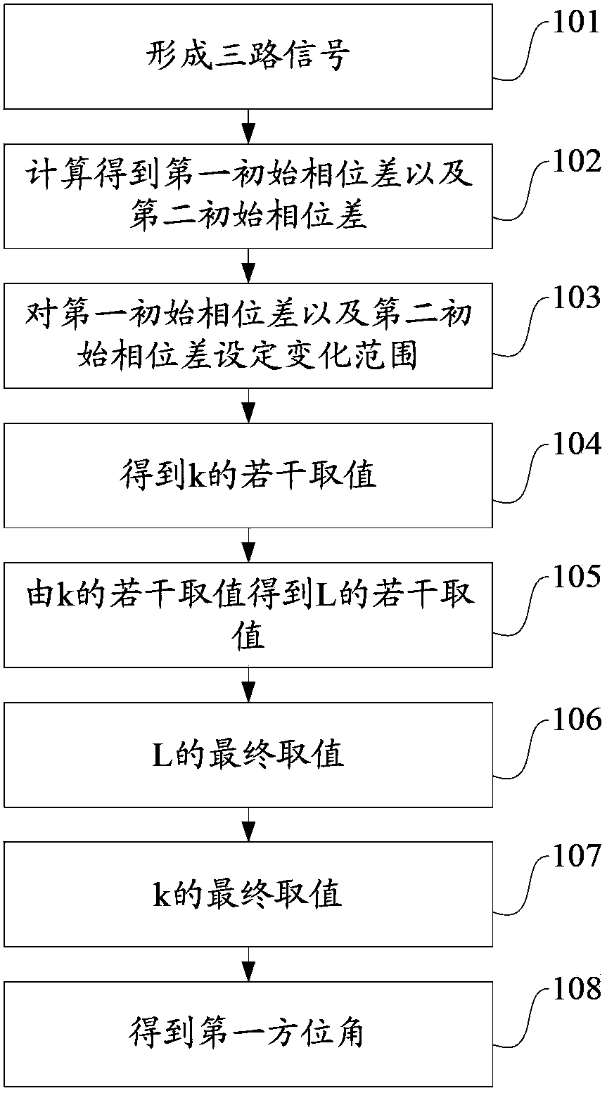
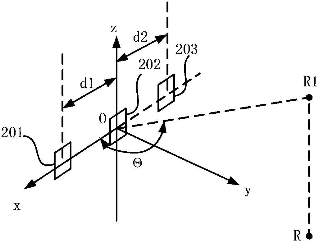
[0040] This embodiment provides a communication control method based on a phased array antenna system. It mainly realizes precise positioning of the OBU by receiving wireless signals from the OBU, and combines the acquired coordinates of the OBU with the pre-stored coordinate system in the control device. Compare the set area to judge whether the OBU is in the preset area, if so, control the RSU and OBU to conduct transaction communication, otherwise prohibit the RSU and OBU to conduct transaction communication. The preset area in the coordinate system corresponding to the above-mentioned antenna system and the position of the OBU are all obtained by the following positioning method. For the positioning method of this embodiment, please refer to figure 1 , the positioning method is based on an antenna system, which may be a phased array antenna system. Specifically, such as figure 2 As shown, the antenna system includes the first antenna 201 (or called the first antenna sub-...

Embodiment 2

[0077] This embodiment adds the following content on the basis of Embodiment 1:

[0078] In the antenna system of this embodiment, another group of antennas is added, such as Figure 4 As shown, with the second antenna 202 as the origin, the fourth antenna 401 and the fifth antenna 402 with the same specification and uniform orientation as the second antenna 202 are arranged on both sides of the second antenna 202 on the third coordinate axis z. There is a third interval d3 between 401 and the second antenna 202, and there is a fourth interval d4 between the second antenna 202 and the fifth antenna 402. D3 and d4 satisfy the following relationship: d3 / d4=r / s, r and s are A positive integer that is relatively prime and the value is not 1. The second coordinate axis y and the third coordinate axis z form a second projection plane. The target device R is positively projected onto the second projection plane to form a second projection point R2. The second projection The second a...

Embodiment 3

[0101] This embodiment adds the following content on the basis of embodiment two:

[0102] The positioning method of this embodiment also includes: according to the installation height of the second antenna 202, the angle between the plane where the second antenna 202 is located and the horizontal plane, the angle between the plane where the second antenna 202 is located and the horizontal plane, θ and α, and calculate the target The coordinates of the device R in the coverage area in front of the vertical projection point of the second antenna 202 . Such as Figure 7 As shown, the longitudinal distance H from the target device to the antenna system can be determined by the second azimuth α of the target device 1 , calculated as follows:

[0103] Obtain the above-mentioned second azimuth α, the angle β between the plane where the second antenna is located and the horizontal plane (generally the installation angle of the antenna system), and the installation height h of the s...


PUM


Abstract

The invention discloses a positioning method and device and a communication control method and system. An antenna system at least comprises at least three antennas, and the interval between the adjacent antennas meets a certain relationship. The positioning method is characterized by receiving the same wireless signal from a target device through each antenna to obtain each path of signals respectively and calculating a first initial phase difference between the obtained first path of signals and the second path of signals and a second initial phase difference between the obtained second path of signals and the third path of signals; setting adjustment range for the first initial phase difference and the second initial phase difference to determine the final value of the first initial phase difference after adjustment; obtaining an azimuth angle according to the relation between the final and real first phase difference and the azimuth angle; determining the coordinate of the target device according to the azimuth angle to positioning the target device precisely; and determining a communication area of an RSU and an OBU precisely according to the coordinate of the target device, thereby preventing the problem of adjacent channel interference.

Description

technical field [0001] The present application relates to the communication field, and in particular to a positioning method, a communication control method, device and system. Background technique [0002] Electronic Toll Collection (ETC) is a specific application of Intelligent Transportation System (ITS). In the current ETC lane, in order to ensure a high speed of vehicles, the communication range between the Road-side Unit (RSU) and the On-board Unit (OBU) is about 10 meters in front of the automatic railing Since the elliptical range is generally large and covers adjacent lanes, when the RSU in the current lane receives the uplink signal from the OBU in the adjacent lane, it will cause adjacent channel interference. [0003] At present, in order to solve the problem of adjacent channel interference, ETC equipment manufacturers generally set the RSU and OBU of a certain size at the boundary point by restricting the necessary conditions on the RSU antenna RF index and an...

Claims


Application Information

Patent Timeline
Patent Type & Authority Applications(China)
IPC IPC(8): G01S5/02G07B15/06
CPCG01S5/04G07B15/06
Inventor 张学诚林树亮杨耿吴荣华
Owner SHENZHEN GENVICT TECH
Why Eureka
Try Eureka