Eureka AIR delivers breakthrough ideas for toughest innovation challenges, trusted by R&D personnel around the world.

Laser light source and projection device

A laser light source and laser technology, applied in the field of light sources, can solve the problems of complex light source structure, light loss, large size, etc., and achieve the effect of small size and compact optical structure

Active Publication Date: 2015-02-04
杨毅
View PDF8 Cites 9 Cited by
  • Summary
  • Abstract
  • Description
  • Claims
  • Application Information

AI Technical Summary

Problems solved by technology

[0006] However, due to the presence of spectroscopic filters, the structure of the entire light source becomes complex and bulky, which is not conducive to the current development trend of miniaturization of light sources.
In addition, the spectral filter will filter out the remaining excitation light in the outgoing light, which is also a part of light loss.

Method used


Image

  • Laser light source and projection device
  • Laser light source and projection device
  • Laser light source and projection device

Examples


Embodiment Construction

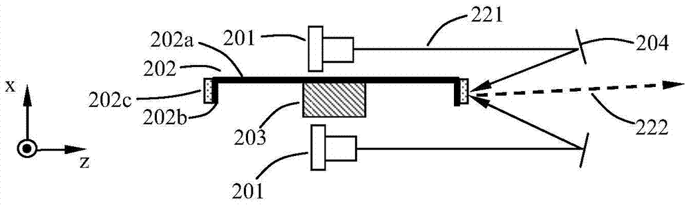
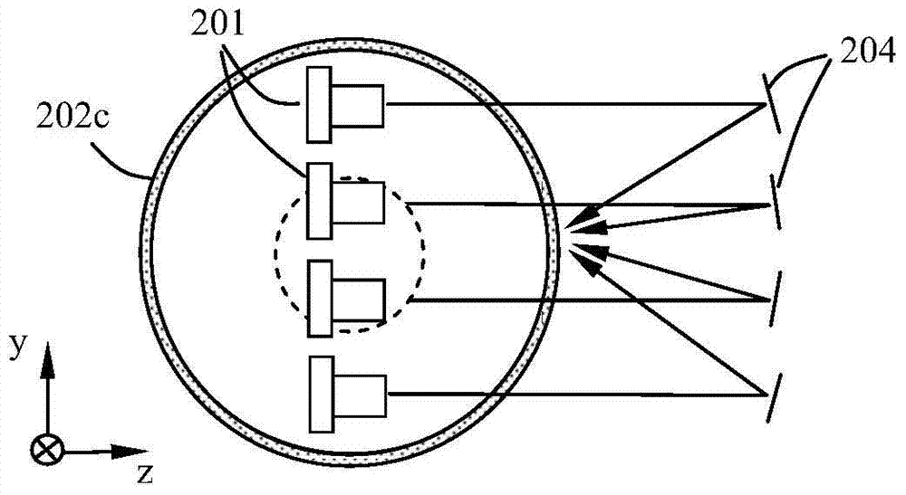
[0020] The present invention proposes a laser light source, its structural schematic diagram is as follows Figure 2A , 2B and 2C. Figure 2A , 2B and the left side of 2C are respectively marked with a schematic diagram of the Cartesian coordinate system: Figure 2A Upward in the center is the x direction, rightward is the z direction, and the vertical paper surface is the y direction outward; Figure 2B Upward in the center is the y direction, rightward is the z direction, and vertical to the inside of the paper is the x direction; Figure 2C Upward in the center is the y direction, rightward is the x direction, and the vertical paper surface is the z direction outward. Figure 2A , 2B Both 2C and 2C use the same coordinate system, which shows the viewing orientation of the three schematic diagrams. It is worth noting that the legends of all embodiments in the present invention use the same coordinate system, and the coordinate systems identified in the following figure...


PUM


Abstract

The invention provides a laser light source and a projection device. The laser light source comprises a laser diode array used for emitting laser along a first direction and a wavelength conversion rotary plate. The plane where the plate surface of the wavelength conversion rotary plate is located is parallel to the first direction. The wavelength conversion rotary plate comprises an annular side wall perpendicular to the plate surface, and the annular side wall is provided with a wavelength conversion layer. The laser light source further comprises a reflecting device used for reflecting the laser emitted along the first direction and converging the laser to the wavelength conversion layer of the annular side wall of the wavelength conversion rotary plate, and a driving device used for driving the wavelength conversion rotary plate to rotate. In the laser light source, the wavelength conversion layer is arranged on the annular side wall of the wavelength conversion rotary plate, so that the plate surface of the wavelength conversion rotary plate can be parallel to the emission direction of laser instead of being vertical to the emission direction of laser like in the prior art. Moreover, the laser diode array and the wavelength conversion rotary plate are disposed at the same side of the reflecting device, which makes the laser light source more compact in optical structure and smaller in size.

Description

technical field [0001] The invention relates to the field of light sources, in particular to a light source using laser technology and a projection device using the laser light source. [0002] Background technique [0003] At present, light source technology has been applied in many fields, and the most widely used light sources are halogen lamps and fluorescent lamps. The biggest problem with these light sources is insufficient brightness. In recent years, the LED light source has developed rapidly. The blue LED is used to excite the yellow phosphor powder coated on the surface of the LED to generate white light. This light source has begun to be popular in the market. But the problem is that the power of a single LED light source is low, and there is still the problem of insufficient brightness. [0004] In the field of high-brightness light sources, high-pressure mercury lamps and xenon light sources are commonly used. Such light sources rely on ultra-short lamp arcs ...

Claims


Application Information

Patent Timeline
Patent Type & Authority Applications(China)
IPC IPC(8): G03B21/20F21V14/00
CPCF21V14/00G03B21/2033G03B21/204
Inventor 杨毅
Owner 杨毅
Why Eureka
Eureka Blog
Learn More