Electroplating copper clad aluminum conductor

A technology of electroplating copper and aluminum cladding, which is applied in the direction of metal/alloy conductors, etc., can solve the problems that the temperature rise of copper wires cannot be monitored, reduce market competitiveness, increase production costs, etc., achieve good product quality, reduce line loss, and strengthen The effect of online monitoring

Inactive Publication Date: 2015-02-04
印培东
View PDF5 Cites 3 Cited by
  • Summary
  • Abstract
  • Description
  • Claims
  • Application Information

AI Technical Summary

Problems solved by technology

[0003] As we all know, the important position and role of the copper wire industry in the development of the national economy are becoming more and more prominent, but most of the traditional pure copper enameled wires use pure copper materials, but due to the shortage of resources, the price of pure copper is relat

Method used


Image

  • Electroplating copper clad aluminum conductor

Examples


Embodiment 1

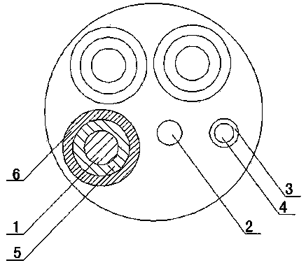
[0011] An electroplated copper-clad aluminum wire, which has a circular aluminum-magnesium body 1, and the wire composed of a plurality of circular aluminum-magnesium bodies 1 is a circular base core, and a piece engraved with The grating fiber 2 of the temperature measuring grating and a soft copper tube of the cooling channel. A grating temperature measuring point is formed on the grating optical fiber 2 every predetermined distance. The soft copper tube of the cooling channel is a soft copper tube 4 with an insulating film wrapping layer 3 having the same length as the round aluminum-magnesium body 1 . The outer layer of the circular aluminum-magnesium body 1 is provided with a tin layer 5 , and a copper plating solution 6 is electroplated between the circular aluminum-magnesium body 1 and the tin layer 5 . The formula of the copper plating solution 6 is: 40-50 g / L of one of copper nitrates, 120-150 g / L of hydroxybutylene diphosphonic acid, 2-5 g / L of methylaminodimethylid...

Embodiment 2

[0013] An electroplated copper-clad aluminum wire, which has a circular aluminum-magnesium body 1, and the wire composed of a plurality of circular aluminum-magnesium bodies 1 is a circular base core, and a piece engraved with The grating fiber 2 of the temperature measuring grating and a soft copper tube of the cooling channel. A grating temperature measuring point is formed on the grating optical fiber 2 every predetermined distance. The soft copper tube of the cooling channel is a soft copper tube 4 with an insulating film wrapping layer 3 having the same length as the round aluminum-magnesium body 1 . The outer layer of the circular aluminum-magnesium body 1 is provided with a tin layer 5 , and a copper plating solution 6 is electroplated between the circular aluminum-magnesium body 1 and the tin layer 5 . The formula of the copper plating solution 6 is: 30-40 g / L of copper nitrate, 100-130 g / L of hydroxybutylene diphosphonic acid, 1-4 g / L of methylammonium dimethylene ph...


PUM


Abstract

The invention relates to an electroplating copper clad aluminum conductor. The electroplating copper clad aluminum conductor is provided with round aluminum and magnesium bodies. A conductor composed of a plurality of the round aluminum and magnesium bodies is provided with a round base core. An optical grating optical fiber with temperature measurement optical gratings carved on and a cooling channel soft copper pipe are arranged in the round base core. Optical grating temperature measuring points are formed on the optical grating optical fiber at predetermined intervals. The cooling channel soft copper pipe is a soft copper pipe with an insulation film wrapping layer and of the same length as the round aluminum and magnesium bodies. Tin layers are arranged on the external layers of the round aluminum and magnesium bodies. Copper plating liquid is electroplated between each round aluminum and magnesium body and each tin layer. The formula of the copper plating liquid consists of 30-50g/L of one type of copper nitrate, 100-150g/L of hydroxyl butyl diphosphonate, 1-5g/L of methylene phosphonic acid, 5-10g/L of tripotassium citrate, 0.01-0.05g/L of polyethyleneimine, 0.02-0.08g/L of phenylurea and the balance water.

Description

[0001] technical field [0002] The invention relates to a metal wire, in particular to an electroplated copper-clad aluminum wire. Background technique [0003] As we all know, the important position and role of the copper wire industry in the development of the national economy are becoming more and more prominent, but most of the traditional pure copper enameled wires use pure copper materials, but due to the shortage of resources, the price of pure copper is relatively high, which increases production costs and reduces market competition. force. In addition, the temperature rise of the copper conductor cannot be monitored during operation, and it is easy to cause the temperature rise caused by the increase of the power conductor load to cause damage to the entire cable. Contents of the invention [0004] The technical solution adopted by the present invention to solve the technical problem is: an electroplated copper-clad aluminum wire, which has a circular aluminum-m...

Claims


Application Information

Patent Timeline
IPC IPC(8): H01B1/02C25D3/38C25D7/06
Inventor 不公告发明人
Owner 印培东
Why Eureka
Try Eureka