
Combined split conductor

A combination of split and conductor technology, applied in the direction of power cables, electrical components, fiber mechanical structures, etc., can solve the problems of increased line loss, increased processing difficulty, uneven electric field, etc., to achieve uniform electric field, increase line loss, and reduce processing difficulty Effect

Inactive Publication Date: 2015-02-04
WUXI JIANGNAN CABLE
View PDF8 Cites 5 Cited by
  • Summary
  • Abstract
  • Description
  • Claims
  • Application Information

AI Technical Summary

Problems solved by technology

In the prior art, there is a structure in which stainless steel tubes or other metal tubes are arranged outside the optical fiber. For example, Chinese patent CN201220468863.8 discloses a cable that can detect the operating state. The optical fiber is used to transmit signals. The stainless steel tube is coated outside the optical fiber. Stranded in the center of the cable conductor; the thicker the stainless steel tube of this structure, the larger the outer diameter, the larger the space required, the larger the central angle (vertex angle) of the fan-shaped strand, and the greater the processing difficulty, the stainless steel tube and fan-shaped The gap between the strands is also larger; if the outer diameter of the stainless steel tube is too small, the diameter of the steel tube will inevitably be small, and the torsional force and tensile force that can withstand are still small, and it will be crushed, the optical fiber will be broken, or the twisted Breaking or pulling off the optical fiber; when the corrugated strands divide the conductor, the patented structure cannot be used because it is a hollow structure; at the same time, the stainless steel tube or other metal tubes will also cause uneven electric field and increase line loss

Method used


Image

  • Combined split conductor
  • Combined split conductor
  • Combined split conductor

Examples


Embodiment Construction

[0021] The present invention will be further described below in conjunction with accompanying drawing.

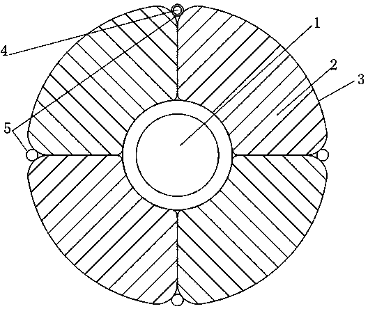
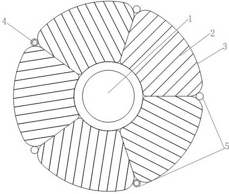
[0022] like figure 1 The shown combined segmented conductor with built-in optical fiber includes a central support strand 1, and the conductor structure is composed of several corrugated conductor strands 2 and the central support strand 1; the four corrugated conductor strands The block 2 surrounds the central support strand 1 around the central support strand 1; the corrugated conductor strands 2 are provided with insulating crepe paper 3 isolating each strand; the corrugated conductor strands 2 Four wire bundles 5 are arranged between the fan-shaped corners of the conductor strands, and an optical fiber unit 4 is directly dragged in the center of one of the wire bundles.

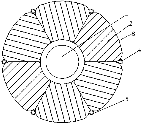
[0023] like figure 2 A combined segmented conductor with built-in optical fiber is shown, including a central support strand 1, and the conductor structure is composed of several corrugated conducto...


PUM


Abstract

The invention discloses a combined split conductor. The combined split conductor comprises a central support strand block, and the conductor structure is composed of a plurality of corrugated conductor strand blocks and the central support strand block in an integrating mode; the corrugated conductor strand blocks surround the central support strand block around the central support strand block; insulating crepe paper for separating the strand blocks is arranged between the corrugated conductor strand blocks; at least one silk thread bundle with an optical fiber unit at the center in a direct towing mode is arranged between the fan-shaped angles of the corrugated conductor strand blocks. The combined split conductor is capable of monitoring the temperature and transmission load of a power cable in real time and serving as a large-section conductor in integration of three networks, intelligent cable, extra-high-tension power cable and high-tension power cable; the silk thread bundle effectively protects the optical fiber unit, when processing and paving, the optical fiber unit is protected from extrusion, and in particular, when running the cable, the cable would generate heat and swell up, the space for holding the optical fiber can be guaranteed, and the cable can run normally.

Description

[0001] technical field [0002] The invention relates to the field of cable conductors, in particular to a combined split conductor with built-in optical fibers. Background technique [0003] With the rapid growth of China's economy and the further acceleration of industrialization and urbanization, the requirements for the construction of infrastructure such as urban power grids are increasing. Cities in developed regions and provincial capitals have required the use of underground power cables to transmit electric energy in urban centers. At the same time, electricity is the premise and foundation of the development of the national economy. With the rapid development of the national economy, the demand for electricity has increased sharply, the capacity of the grid has increased sharply, and the power of motors has increased. ) The transmission direction develops; in order to increase the carrying capacity of the cable, the method of increasing the conductor cross sect...

Claims


Application Information

Patent Timeline
Patent Type & Authority Applications(China)
IPC IPC(8): H01B9/00G02B6/44
Inventor 马壮韩俊杰张文敏柳欣高天磊
Owner WUXI JIANGNAN CABLE
Learn More