
A Correction Method Based on Six-Pulse Algorithm to Realize the Installation Position Deviation of Hall Sensor

A technology of Hall sensor and installation position, applied in the direction of controlling electromechanical transmission, controlling electromechanical brake, controlling generator, etc., can solve the problems of ineffective manual error correction, bottleneck of large-scale promotion and use, and increase of input cost, etc. Improve the correction effect, avoid human installation errors, and reduce the effect of input costs

Active Publication Date: 2017-03-01
JIANGSU HAOFENG AUTO PARTS
View PDF4 Cites 0 Cited by
  • Summary
  • Abstract
  • Description
  • Claims
  • Application Information

AI Technical Summary

Problems solved by technology

[0004] (1) There are inevitable errors in human installation;
[0005] (2) Instruments and equipment are too expensive, increasing input costs;
[0006] (3) The effect of manual error correction is not obvious, and the correction rate is low
[0007] Therefore, the current correction method for the installation position deviation of the Hall sensor still has certain defects, which brings certain bottlenecks to large-scale promotion and use.

Method used


Image

  • A Correction Method Based on Six-Pulse Algorithm to Realize the Installation Position Deviation of Hall Sensor
  • A Correction Method Based on Six-Pulse Algorithm to Realize the Installation Position Deviation of Hall Sensor
  • A Correction Method Based on Six-Pulse Algorithm to Realize the Installation Position Deviation of Hall Sensor

Examples


Embodiment Construction

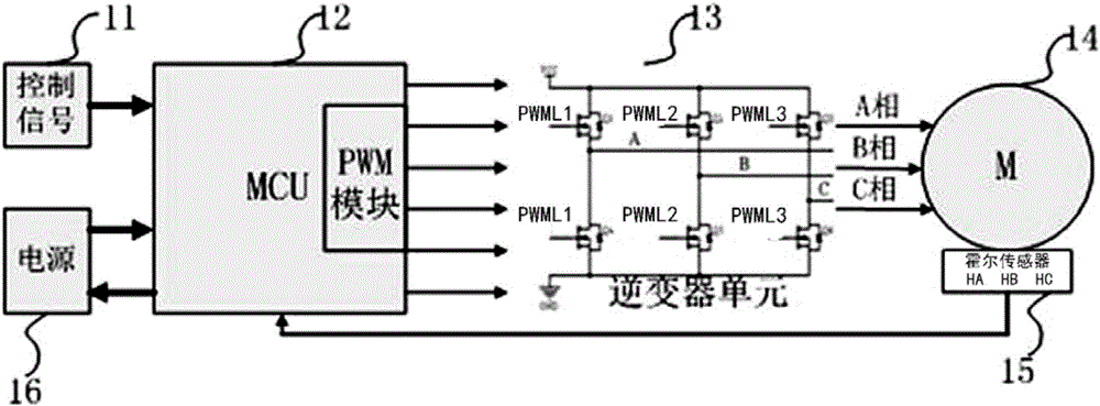
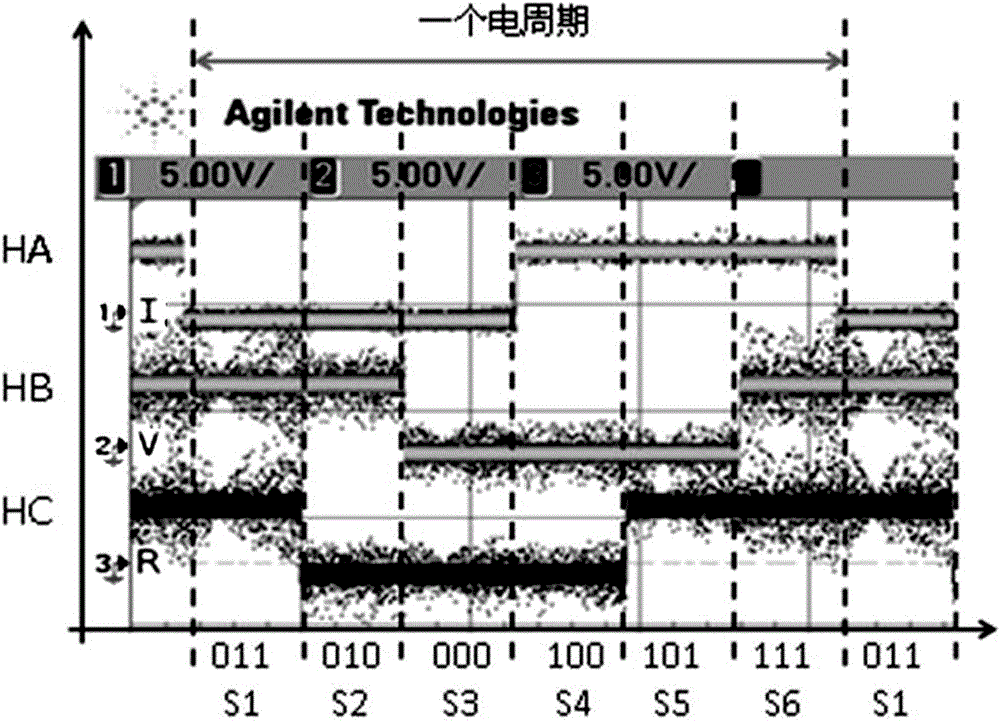
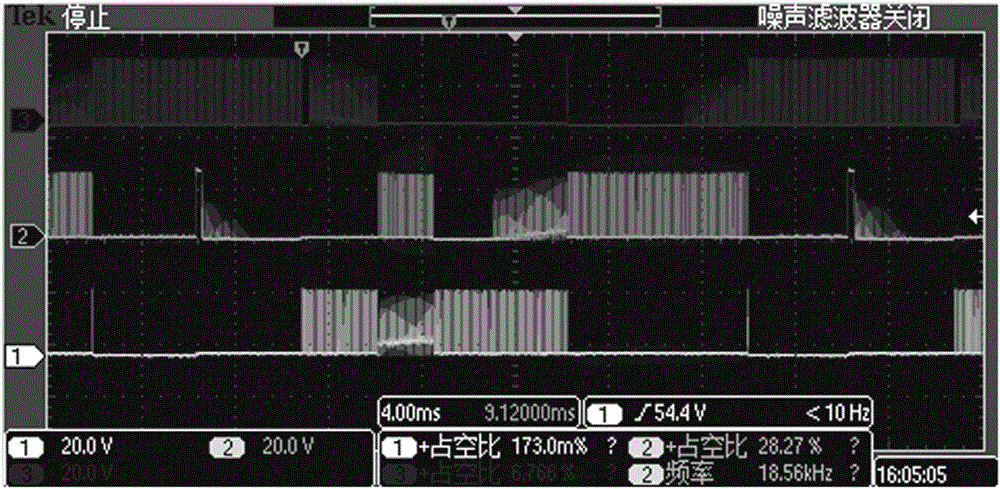
[0036] Attached below Figure 1-Figure 7 The present invention is further illustrated with specific examples.

[0037] The steps to implement the correction method for the installation position deviation of the Hall sensor are as follows:

[0038] (1). If figure 1 As shown, the control signal 11 is input into the MCU module 12, the power supply 16 supplies power for the system, and the signal output by the MCU module realizes the control of the motor 14 through the inversion of the inverter unit; the output duty of the PWM module in the MCU module 12 is set Ratio D=10%, execution time Ti=100ms;

[0039] (2). Set the relative installation electrical angle α of the three Hall sensors HA, HB, and HC in the Hall sensor group 15, α=60° (or 120°), and determine the pole pair number N of the controlled object motor = 5;

[0040] (3). Fix the three Hall sensors HA, HB, and HC according to the mechanical angle of α / N=60° / 5=12°, and then fix the three Hall sensors fixed on the stat...


PUM


Abstract

The invention belongs to the technical field of a brushless direct current motor and specifically relates to a method for realizing Hall sensor installation position deviation correction based on six pulse algorithm so as to realize correct phase commutation of Hall sensors of the motor. Under the premise of not depending on human sensor position finding, not needing the help of a detection device and not needing human correction mode, the correction of position deviation of the Hall sensors is realized directly through the six pulse algorithm, so that phase commutation can be realized at the phase commutation point accurately; the algorithm is simple and easy to realize; transportability is high; and development cost and maintenance cost are reduced.

Description

technical field [0001] The invention belongs to the technical field of brushless direct current motors, and in particular relates to a method for correcting the installation position deviation of a Hall sensor based on a six-pulse algorithm, so as to realize correct phase commutation of the Hall sensor of the motor. Background technique [0002] Brushless DC motor (Brusless DC motor, hereinafter referred to as BLDCM) is widely used in the field of industrial automation due to its good output torque characteristics, efficient power utilization, intelligent control, and long service life. BLDCM relies on electronic commutation, so it is necessary to accurately find the commutation position to ensure stable and efficient output of the motor. If the BLDCM commutation point is ahead or lags behind, it will easily cause the utilization rate of electric energy of the motor to decrease, the system will not work stably, and even bring irreversible harm to the system in severe cases. ...

Claims


Application Information

Patent Timeline
Patent Type & Authority Patents(China)
IPC IPC(8): H02P21/18
Inventor 伍春生刘吉超陈朋朱建方
Owner JIANGSU HAOFENG AUTO PARTS
Learn More