Workpiece clamping device applied to horizontal lathe

A horizontal lathe and workpiece clamping technology, applied in positioning devices, metal processing mechanical parts, clamping and other directions, can solve the problems of severe workpiece runout and difficulty in ensuring the accuracy of the inner hole of the workpiece, so as to improve processing efficiency, ensure stability, The effect of improving machining accuracy

Active Publication Date: 2015-02-11
RONGCHENG METAL FORMING MACHINE GROUP
View PDF5 Cites 4 Cited by
  • Summary
  • Abstract
  • Description
  • Claims
  • Application Information

AI Technical Summary

Problems solved by technology

Since there is no clamping device on the top of the workpiece, the workpiece is processed in a cantilever state. During the processing, the workpiece jumps violently in the circumferential direction, which makes it difficult to guarantee the accuracy of the inner hole of the workpiece.

Method used


Image

  • Workpiece clamping device applied to horizontal lathe
  • Workpiece clamping device applied to horizontal lathe
  • Workpiece clamping device applied to horizontal lathe

Examples


Embodiment Construction

[0018] The present invention will be further described below in conjunction with the accompanying drawings and embodiments.

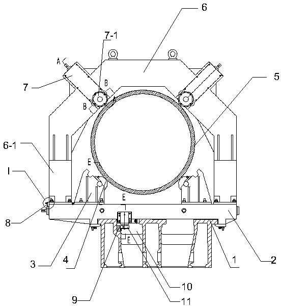
[0019] as attached figure 1 As shown, a workpiece clamping device applied to a horizontal lathe includes a support base plate 2 arranged on the lathe bed surface 1, two movable brackets 3 are arranged on the support base plate, and the bracket 3 is provided with Freely rotatable support roller 4. The bracket 3 can slide left and right on the bed surface 1, and can be locked with the bed surface through bolts.

[0020] as attached figure 1 As shown, when the left and right brackets 3 are moved to a suitable position, the support roller 4 on the bracket 3 can support the workpiece from the bottom of the workpiece 5 . as attached figure 1 As shown, the clamping device described in this embodiment mainly clamps thin-walled cylindrical workpieces. According to the description below, the clamping device can also form stable clamping for workpieces of othe...


PUM


Abstract

The invention aims to provide a workpiece clamping device applied to a horizontal lathe. The workpiece clamping device comprises a supporting baseplate arranged on a lathe surface, wherein two movable brackets are arranged on the supporting baseplate, and support rollers capable of rotating freely are arranged on the brackets. The workpiece clamping device is characterized in that a portal frame is further arranged on the supporting baseplate, vertical plates on two sides of the portal frame are located on the plate surfaces at two ends of the supporting baseplate, adjustable roller devices are arranged on two sides of a top central line of the portal frame respectively, and rollers capable of rotating freely are arranged on the roller devices; and a workpiece is clamped by the two support rollers at the bottom and the two rollers at the top. The clamping device can guarantee the workpiece stability during machining, improves the machining precision, and effectively increases the machining efficiency of the lathe.

Description

[0001] technical field [0002] The invention relates to a workpiece clamping device applied to a lathe, in particular to a workpiece clamping device applied to a horizontal lathe. Background technique [0003] When processing the inner hole of thin-walled cylindrical parts on a horizontal lathe, due to the characteristics of heavy weight, thin wall, and short length, the tailstock of the horizontal lathe cannot be used to fix the workpiece, which greatly reduces work efficiency. At present, the commonly used fixing method is to install a slide plate on the guide rail surface of the bed. There are two movable brackets on the slide plate. The roller holds the lower part of the workpiece for processing. Since there is no clamping device on the top of the workpiece, the workpiece is processed in a cantilever state. During the processing, the workpiece jumps violently in the circumferential direction, which makes it difficult to guarantee the accuracy of the inner hole of the w...

Claims


Application Information

Patent Timeline
Patent Type & Authority Applications(China)
IPC IPC(8): B23Q3/00
CPCB23Q3/065
Inventor 王贺芮珍珍孟繁营张雷
Owner RONGCHENG METAL FORMING MACHINE GROUP
Why Eureka
Try Eureka