
Clamping mechanism with overturn function and method for overturning and translating workpiece

A technology of clamping mechanism and function, applied in the field of clamping mechanism, can solve the problems of increasing the complexity of mechanical gripper equipment cost control circuit design, etc., and achieve the effect of improving market competitiveness and reducing demand

Active Publication Date: 2015-02-11
IND TECH RES INST
View PDF8 Cites 11 Cited by
  • Summary
  • Abstract
  • Description
  • Claims
  • Application Information

AI Technical Summary

Problems solved by technology

However, the increase in the number of drive components will increase the equipment cost of the mechanical gripper and the design complexity of the control circuit

Method used


Image

  • Clamping mechanism with overturn function and method for overturning and translating workpiece
  • Clamping mechanism with overturn function and method for overturning and translating workpiece
  • Clamping mechanism with overturn function and method for overturning and translating workpiece

Examples


Embodiment Construction

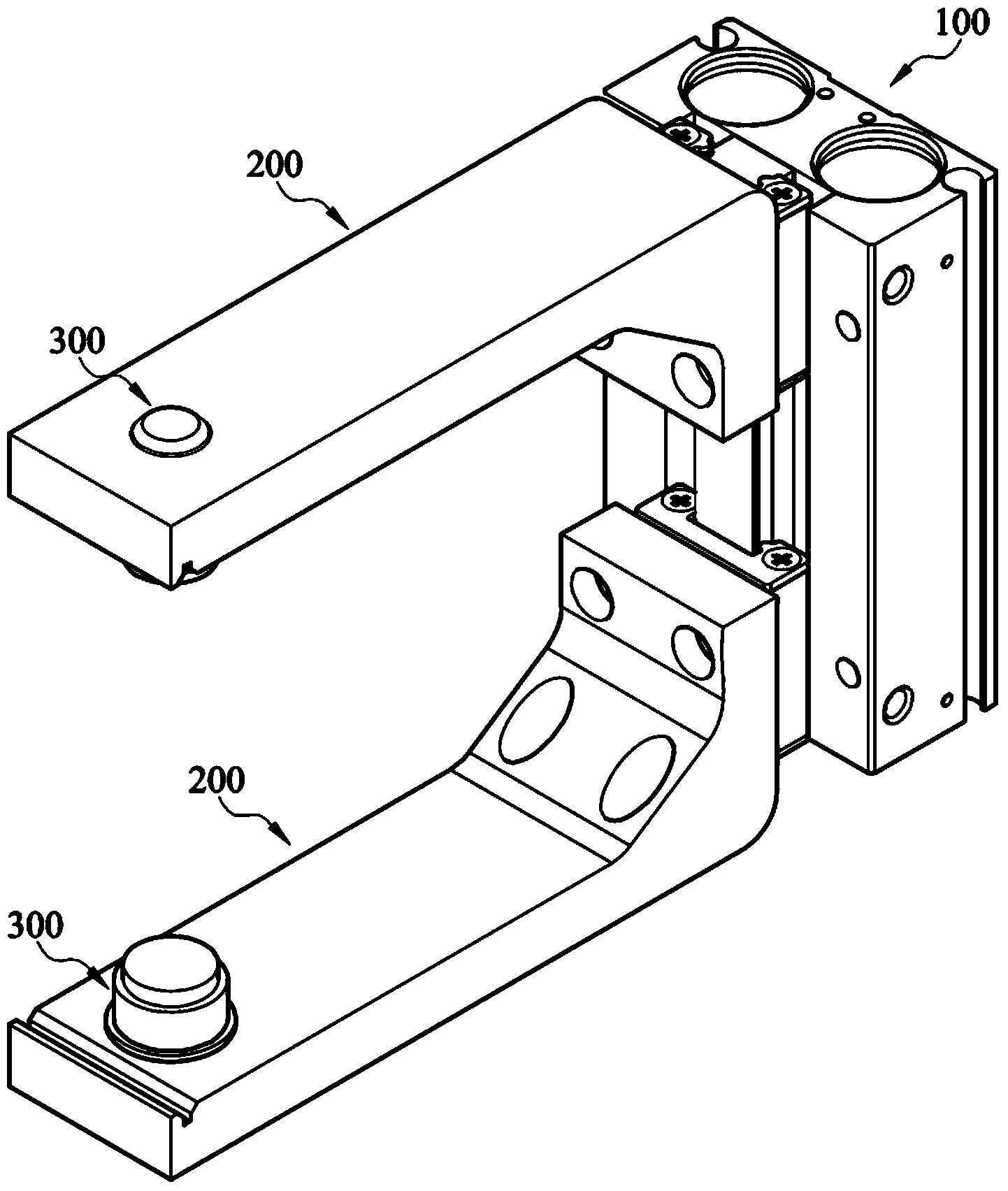
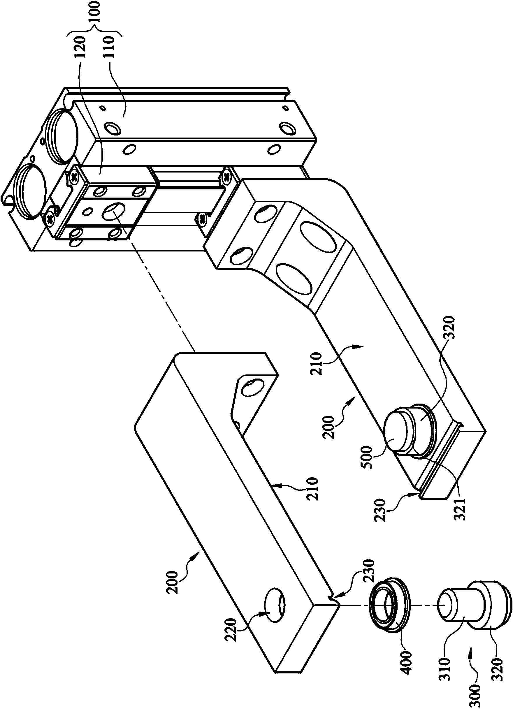
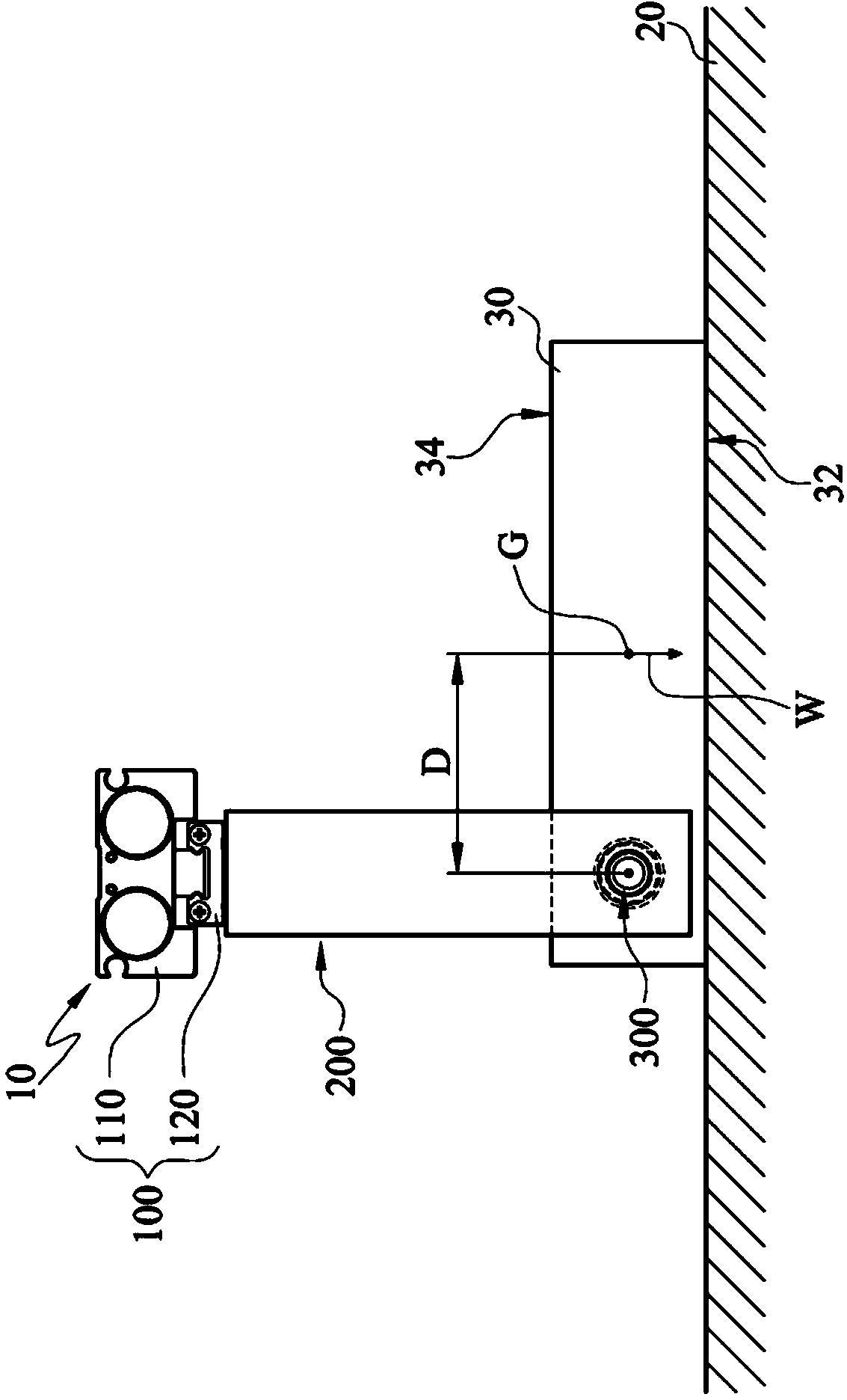
[0039] Please refer to Figure 1 to Figure 3 , figure 1 is a three-dimensional schematic diagram of a clamping mechanism with a flip function according to an embodiment of the present invention, figure 2 for figure 1 The decomposition diagram. image 3 for figure 1 A plan view of a workpiece clamped by the clamping mechanism with flipping function.

[0040] The clamping mechanism 10 with turning function of this embodiment is used to translate or turn over a workpiece 30 . The clamping mechanism 10 includes a base 100 , two movable jaws 200 , two non-powered clamping shafts 300 and two bearings 400 .

[0041] The base body 100 includes a sliding rail 110 and two sliding blocks 120 . The two sliding blocks 120 are respectively slidably disposed on the sliding rail 110 . The driving method between the slider 120 and the sliding rail 110 is, for example, pneumatic driving, hydraulic driving or electric driving.

[0042] The two movable claws 200 are respectively disposed...


PUM


Abstract

The invention discloses a clamping mechanism with an overturn function and a method for overturning and translating a workpiece. The clamping mechanism comprises a base, two movable claws and two unpowered clamping shafts. The two movable claws can be movably arranged on the base. Each movable claw is provided with a wall surface and a shaft hole. The two wall surfaces are opposite to each other, and the two shaft holes are respectively arranged in the two wall surfaces. Each unpowered clamping shaft comprises a pivot part and a clamping part which are connected. The two pivot parts are respectively pivoted on the two shaft holes, and the two unpowered clamping shafts can respectively rotate relative to the two movable claws.

Description

technical field [0001] The invention relates to a mechanical clamp, in particular to a clamping mechanism with a turning function. Background technique [0002] At present, double-sided processing is often required in many manufacturing processes, such as surface mount processing or circuit layout processing. The process of double-sided machining is to perform first-side machining on the surface of a workpiece. Next, the gripper is used to turn the workpiece over for machining on the second side. Wherein, the mechanical jaw generally used to turn over the workpiece includes two clamping parts, two rotating parts, a displacement driving component and a rotating driving component. The two rotating parts are rotatably arranged on the two clamping parts. The displacement driving assembly can drive the relative displacement of the two clamping parts so that the two rotating parts can clamp the workpiece. The rotary driving assembly can drive the two rotating parts to rotate r...

Claims


Application Information

Patent Timeline
IPC IPC(8): B25J15/08
Inventor 李敏豪杨政城黄一萍李雅萍
Owner IND TECH RES INST
Features
  • Generate Ideas
  • Intellectual Property
  • Life Sciences
  • Materials
  • Tech Scout
  • Unparalleled Data Quality
  • Higher Quality Content
  • 60% Fewer Hallucinations
Learn More