
Universal circuit board test system

A test system and circuit board technology, applied in the direction of electronic circuit testing, etc., can solve the problems of low degree of automation, non-universal, complicated operation process, etc., and achieve the effect of high degree of automation, convenient operation and strong versatility

Active Publication Date: 2015-02-11
SOUTH CHINA AGRI UNIV
View PDF5 Cites 66 Cited by
  • Summary
  • Abstract
  • Description
  • Claims
  • Application Information

AI Technical Summary

Problems solved by technology

However, traditional circuit board testing instruments are often aimed at single or fixed test equipment for several circuit boards, and there are many obvious deficiencies
First of all, its degree of automation is low: there are many switches on the panel of traditional test instruments, and many switches need to be operated during the test process. The operation process is complicated, the work quality and efficiency are difficult to improve, and the test work is easily affected by human factors, making the test process difficult. Precise control; secondly, its versatility is poor: traditional testing instruments are often aimed at single or fixed test equipment for several circuit boards. When a new circuit board is to be tested, a new circuit board tester needs to be developed Instruments and test equipment for different circuit boards are not interchangeable, and testing and design require specialized technicians
Therefore, traditional manual testing methods and simple self-made testing equipment will be difficult to meet the increasingly high testing requirements for circuit board testing

Method used


Image

  • Universal circuit board test system
  • Universal circuit board test system
  • Universal circuit board test system

Examples


Embodiment Construction

[0026] The present invention will be further described below in conjunction with specific examples.

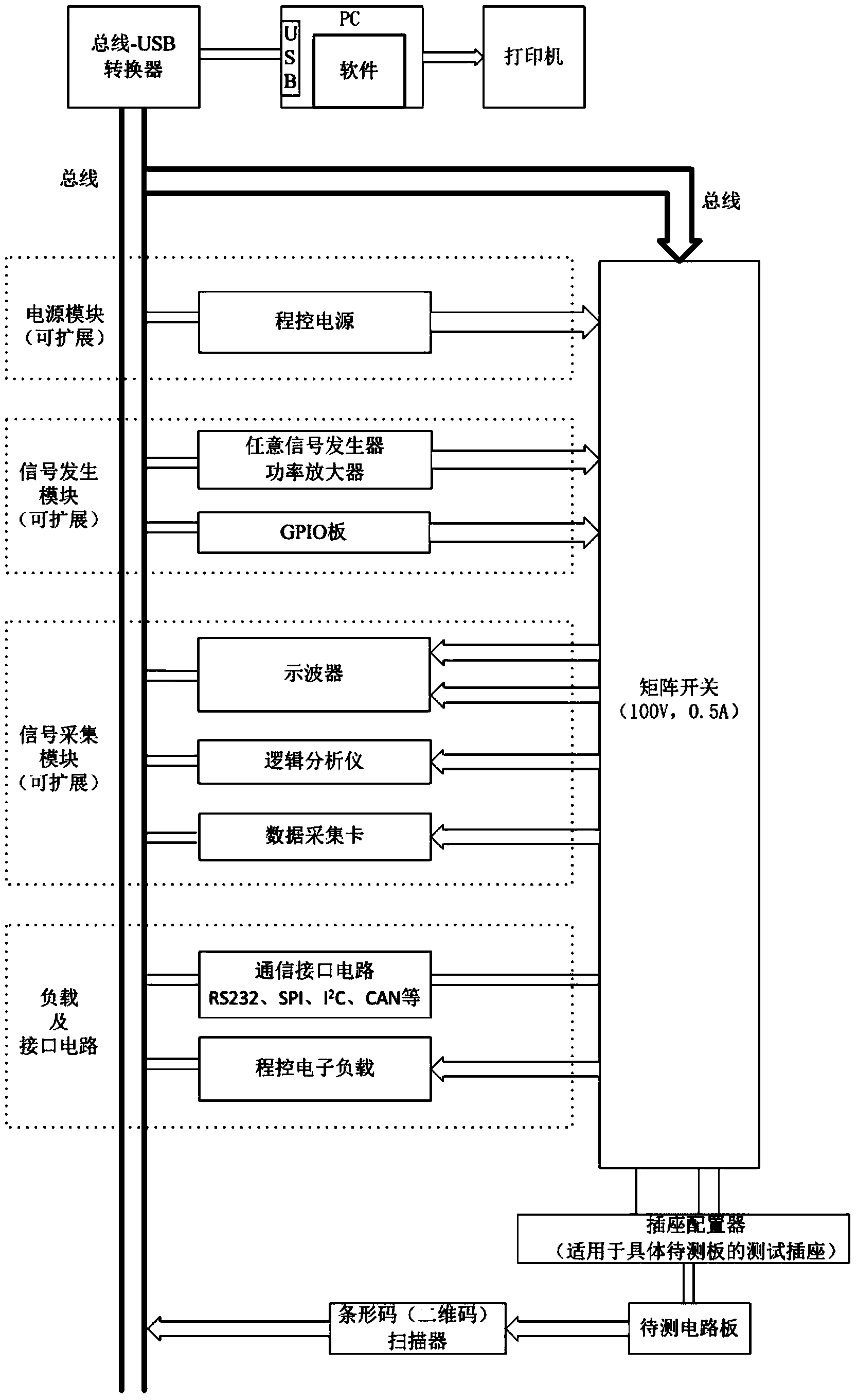
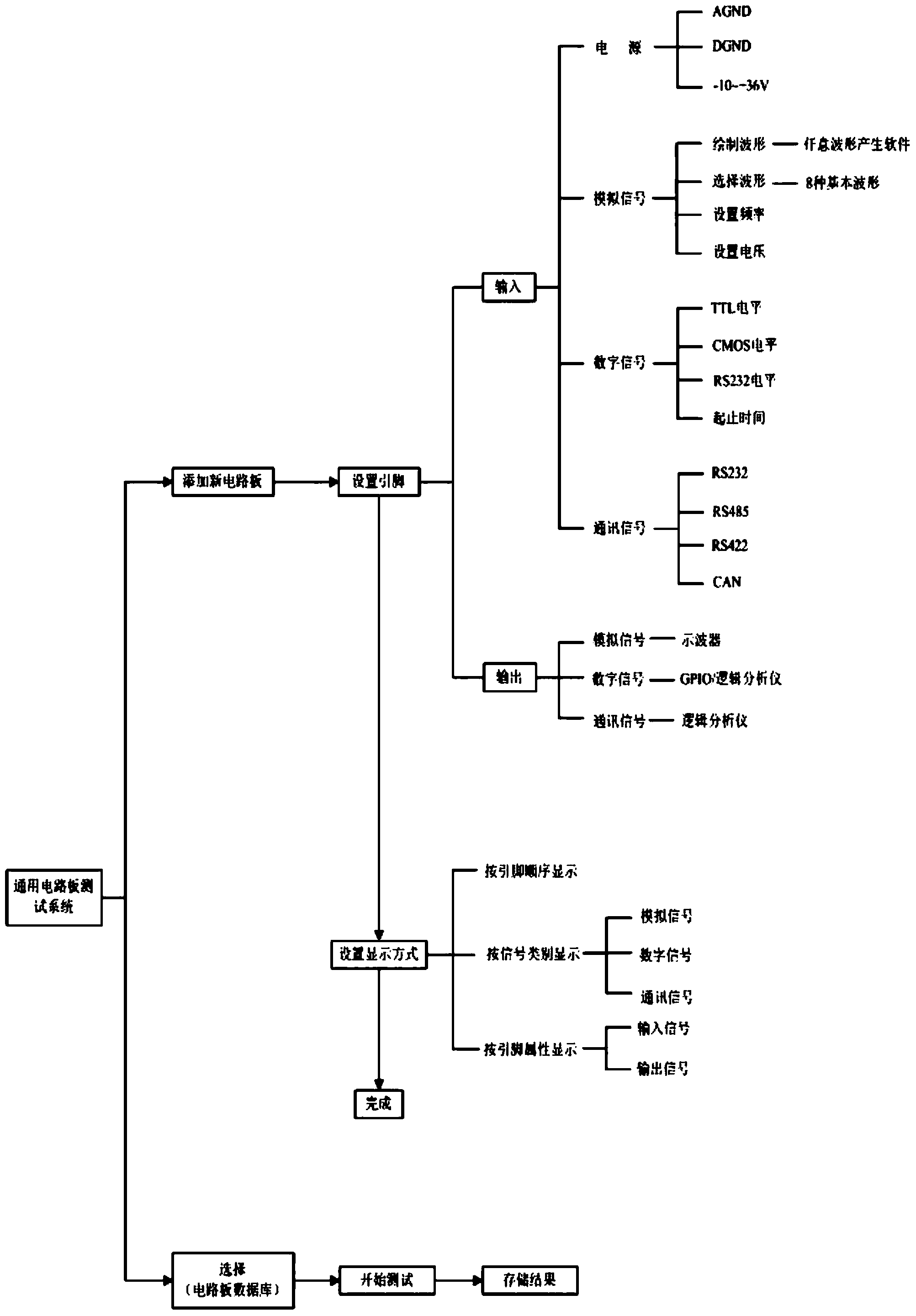
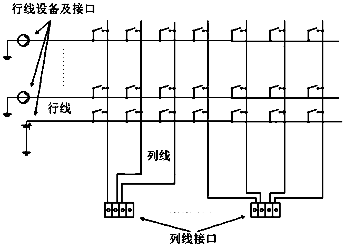
[0027] like Figure 1 to Figure 3 As shown, the general-purpose circuit board testing system described in this embodiment includes two parts, a test machine and a test software, wherein the test machine is used to complete all the hardware of the test task, and has a maximum of 32*32 matrix, row The line and column line can be connected to 32 input and output signals respectively. All hardware parts in the test machine can be expanded or reduced according to actual needs. The test machine includes an automatic test resource and a matrix switch, and the automatic test resource includes an expandable power supply module, an expandable signal generation module, an expandable signal acquisition module, a barcode (two-dimensional code) scanner, and a socket configuration Devices, loads and interface circuits are used to generate stimulus signals and test and analyze response sign...


PUM


Abstract

The invention discloses a universal circuit board test system, which comprises a test machine table and test software, wherein the test machine table comprises automatic test resources and a matrix switch, the automatic test resources are integrated together through a bus and are connected with the matrix switch and a PC (personnel computer) through interfaces, the PC is configured with the test software, the test software outputs a power supply or a signal meeting the requirements through controlling the automatic test resources via the bus, an output signal of a tested circuit board is read, meanwhile, the matrix switch is controlled through the bus so that the corresponding lead pin type in a socket is matched with the lead pin of the tested circuit board, in the work process, the interface definition of the circuit board is added into a test software database, the system automatically switches each lead pin function of the socket for outputting the signal or the power supply conforming to the requirements, in addition, the output interface of the circuit board is automatically connected onto corresponding equipment of the automatic test resources, and the parameters and the waveform of each output interface of the circuit board are displayed through the software interface. The universal circuit board test system has the advantages that the expandability is high, the universality is high, the automation degree is high, the operation is convenient, and the like.

Description

technical field [0001] The invention relates to the technical field of circuit board testing systems, in particular to a general circuit board testing system. Background technique [0002] The circuit board is an indispensable part in the development and production of electronic systems. Its quality directly affects the quality of the complete machine equipment. Its production and inspection cycle affects the development progress and delivery time of the complete machine. Therefore, the test of the circuit board is related to An important link in the quality and production cycle of electronic systems. However, traditional circuit board testing instruments are often aimed at testing equipment for a single or several fixed circuit boards, and there are many obvious deficiencies. First of all, its degree of automation is low: there are many switches on the panel of traditional test instruments, and many switches need to be operated during the test process. The operation proces...

Claims


Application Information

Patent Timeline
IPC IPC(8): G01R31/28
Inventor 孙道宗赵祚喜俞龙姜晟
Owner SOUTH CHINA AGRI UNIV
Learn More