Alignment device

An aligning device and prism technology, applied in the field of semiconductors, can solve problems such as high requirements for prism processing and assembly and adjustment tolerance, difficult gluing of prism groups, etc., and achieve the effects of increasing detection light intensity, simplifying structure, and reducing processing and manufacturing.

Active Publication Date: 2015-02-11
SHANGHAI MICRO ELECTRONICS EQUIP (GRP) CO LTD
View PDF5 Cites 5 Cited by
  • Summary
  • Abstract
  • Description
  • Claims
  • Application Information

AI Technical Summary

Problems solved by technology

The alignment system uses a rotating self-referencing interferometer with multiple main sections and spatial compound prisms. The processing and assembly tolerances of the prisms are very high, and it is difficult to glue the prism groups.

Method used


Image

  • Alignment device
  • Alignment device
  • Alignment device

Examples


Embodiment 2

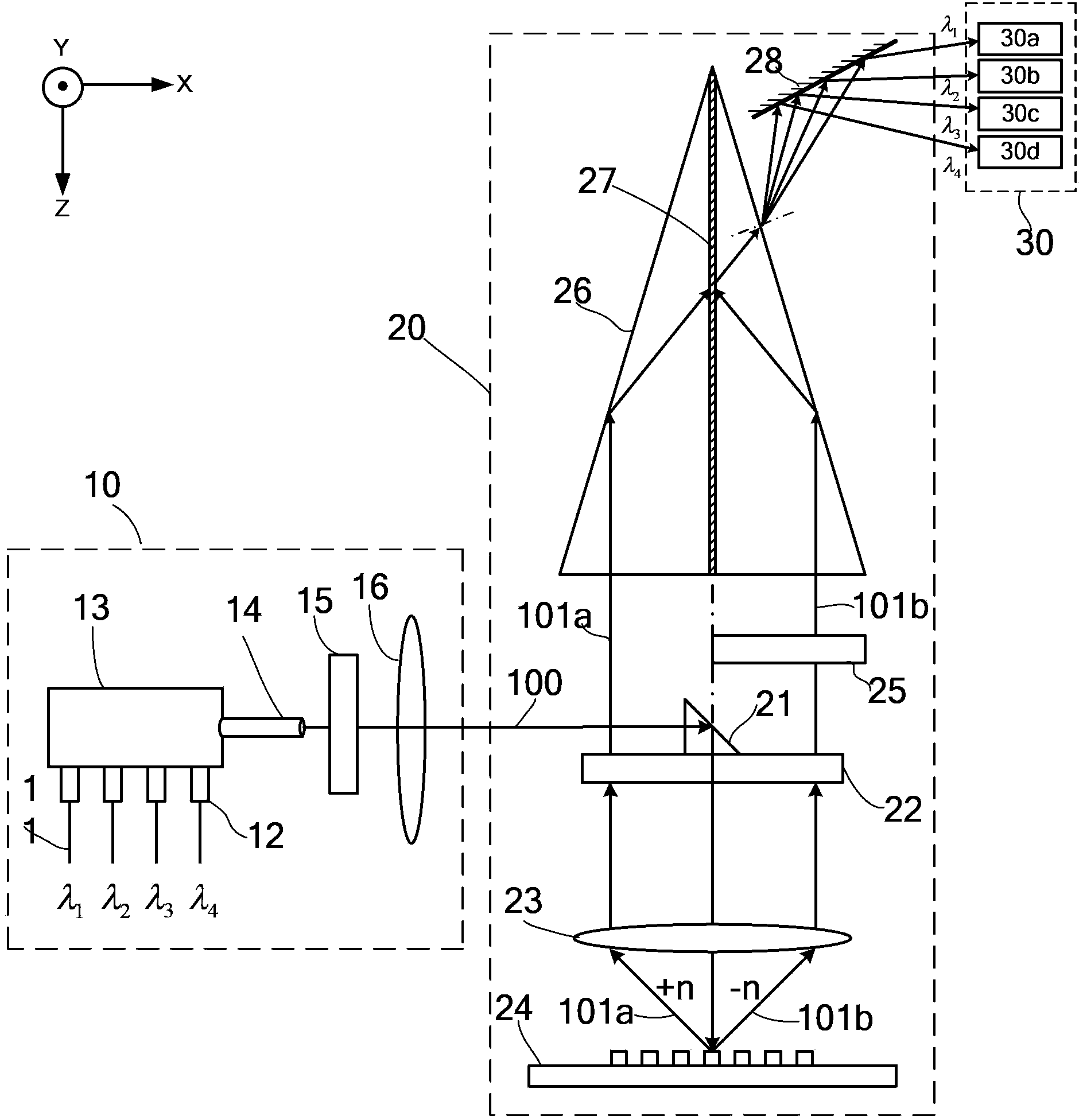
[0070] Please refer to Figure 7 , the difference between this embodiment and Embodiment 1 is that: the number of the detection module 30 is two, the interference module 20 also includes another set of Koster (Koster) prisms 26 and a beam splitter 50, the The positive and negative sub-diffraction lights are divided into two mutually perpendicular diffracted light path parts by the beam splitter 50, and enter two sets of Koster prisms 26 respectively, and then pass through two sets of Koster prisms 26 to form two Part of the detection light, two parts of the detection light are respectively converted into interference signals by the two detection modules and collected, so that the position information of the alignment mark 24 in two directions can be obtained by collecting the information of the interference signals obtained , in this embodiment, that is, the position information in the x direction and the y direction.

[0071] To sum up, the present invention uses the combine...


PUM


Abstract

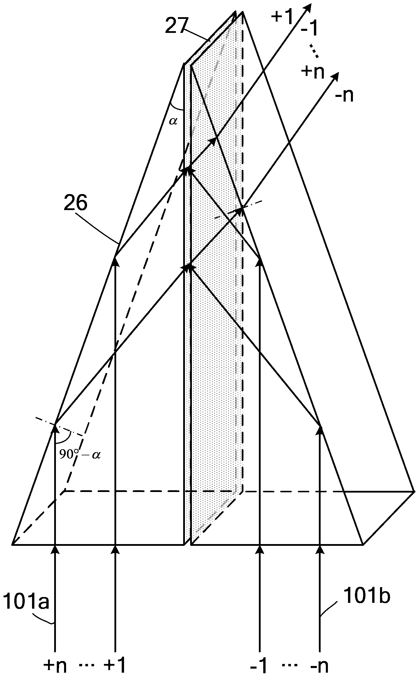
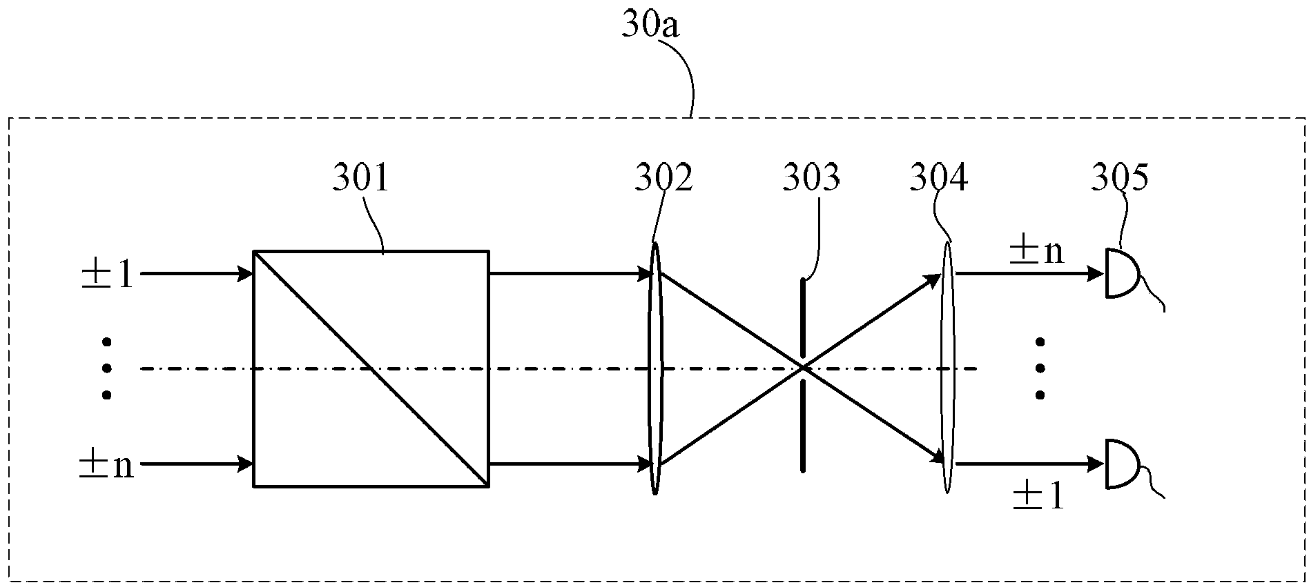
The invention provides an alignment device. The alignment device comprises an illumination module, an interference module and a detection module, wherein the interference module at least comprises a group of Koster prisms; light beams emitted by a light source with a plurality of wavelengths output illumination beams by virtue of the illumination module; the illumination beams are projected to an alignment mark by virtue of the interference module; the interference module is also used for fusing symmetrical positive and negative diffraction light obtained by diffracting the alignment mark by virtue of the Koster prisms to form detection light; and the detection light is converted to interference signals by the detection module and is collected, so that the position information of the alignment mark can be obtained by information of the interference signals obtained by collecting. According to the alignment device, the Koster prisms are used in the interference module. Compared with ridge prisms of polyhedral space structures, so that the processing, manufacturing, mounting and debugging difficulty can be effectively reduced.

Description

technical field [0001] The present invention relates to the field of semiconductors, in particular to an alignment device in photolithography equipment. Background technique [0002] At present, most lithographic equipment adopts an alignment system based on grating diffraction interference. The basic characteristics of this type of alignment system are: the illumination beam containing a single wavelength or multiple wavelengths is irradiated on the grating-type alignment mark to diffract, and the diffracted light of each level carries the position information about the alignment mark; the beams of different orders Spread out from the phase alignment grating at different diffraction angles, and collect the diffracted beams of all levels through the alignment system, so that two symmetrical positive and negative diffraction orders (such as ±1 order, ±2 order, ± order, etc.) The image plane or pupil plane of the alignment system is overlapped and coherent to form interferenc...

Claims


Application Information

Patent Timeline
IPC IPC(8): G03F7/20G03F9/00
Inventor 张鹏黎许琦欣周钰颍
Owner SHANGHAI MICRO ELECTRONICS EQUIP (GRP) CO LTD
Why Eureka
Try Eureka