drive unit for vehicle

A driving device and vehicle technology, which is applied in the direction of power devices, transmission devices, electric power devices, etc., can solve the problems of unfavorable devices such as miniaturization and length increase, and achieve the effect of miniaturization, reduction in the number of parts, and light weight

Active Publication Date: 2016-09-28
HONDA MOTOR CO LTD
View PDF7 Cites 0 Cited by
  • Summary
  • Abstract
  • Description
  • Claims
  • Application Information

AI Technical Summary

Problems solved by technology

[0012] However, since the double pinion type planetary reduction mechanism does not have a sun gear meshing with the second planetary gear 302, the radially inner portion of the second planetary gear 302 becomes a useless space, which is not conducive to downsizing of the device.
[0013] In addition, as disclosed in Patent Document 1, when a double pinion type planetary reduction mechanism and a bevel gear type differential mechanism are arranged in combination, since the carrier and the bevel gear of the double pinion type planetary reduction mechanism The planetary carrier of the type differential mechanism is arranged along the axle direction, so the length in the axial direction becomes large, which is not conducive to the miniaturization of the device

Method used


Image

  • drive unit for vehicle
  • drive unit for vehicle
  • drive unit for vehicle

Examples


Embodiment Construction

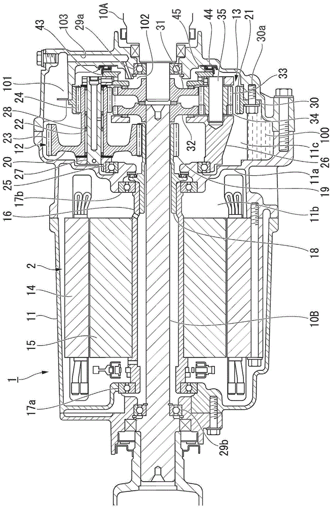
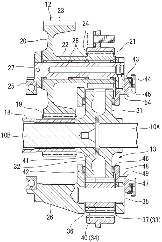
[0039] Below, refer to Figure 1 to Figure 11 The accompanying drawings illustrate embodiments of the vehicle drive device according to the present invention.

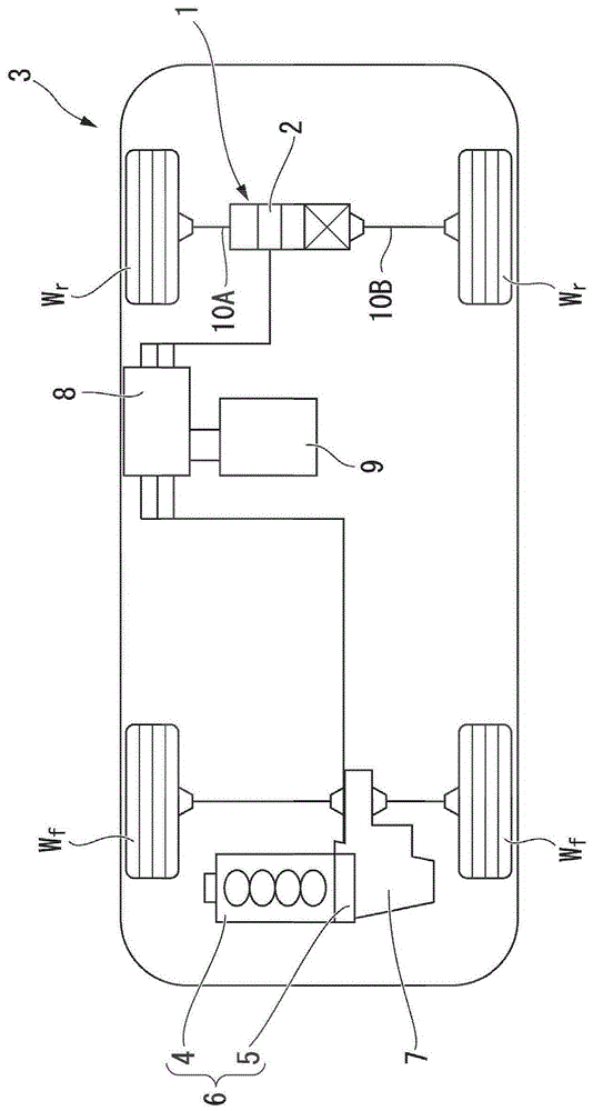
[0040] The vehicle drive device (hereinafter, abbreviated as drive device) 1 according to the present invention uses an electric motor 2 as a drive source for driving wheels, for example, figure 1 It is used in a vehicle 3 with a drive system as shown.

[0041] figure 1 The vehicle 3 shown is a hybrid vehicle having a drive unit 6 in which an internal combustion engine 4 and an electric motor 5 are connected in series. The power of the drive unit 6 is transmitted to the front wheel Wf side via the transmission 7. On the other hand, the power of the drive device 1 according to the present invention provided separately from the drive unit 6 is transmitted to the rear wheel Wr side. The electric motor 5 of the drive unit 6 and the electric motor 2 of the rear wheel Wr side drive device 1 are connected to the battery 9 via ...


PUM


Abstract

The present invention provides a driving device for a vehicle. The driving device for a vehicle includes a first drive shaft and a second drive shaft, a differential mechanism, a speed reduction mechanism, and a housing. The second speed reduction planetary gear of the speed reduction mechanism and the first The planetary gears and the second planetary gears are arranged with phases shifted in the rotational direction, and at least one of the first planetary gears and the second planetary gears of the differential mechanism overlaps with the second reduction planetary gears of the reduction mechanism in the axial direction. s position.

Description

Technical field [0001] The present invention relates to a driving device for a vehicle. [0002] This application claims priority based on Japanese Patent Application No. 2012-040022 for which it applied to Japan on February 27, 2012, and uses the content here. Background technique [0003] As a reduction mechanism capable of arranging the output shaft and the input shaft coaxially, a mechanism using a double pinion type planetary organization has been known (for example, refer to Patent Document 1). Such as Picture 12 As shown, the dual pinion type planetary reduction mechanism is configured such that a first planetary gear 301 and a second planetary gear 302 connected to each other are rotatably mounted on a planet carrier 304 connected to an output shaft 303, and the first planetary gear 301 is the same The sun gear 306 connected to the input shaft 305 meshes with the second planetary gear 302 meshes with the ring gear 308 fixed to the housing 307. [0004] In addition, Patent D...

Claims


Application Information

Patent Timeline
Patent Type & Authority Patents(China)
IPC IPC(8): F16H48/11B60K17/12B60K17/16F16H1/46
CPCB60K17/165B60K17/356F16H48/42B60K2001/001B60K1/02F16H48/11F16H2048/106F16H2200/0021B60K1/00F16H2200/2097F16H37/041F16H48/10
Inventor 大村纯中山茂
Owner HONDA MOTOR CO LTD
Why Eureka
Try Eureka