Robot rescue system used in complicated environment

A complex environment, robot technology, applied in the field of rescue systems, can solve problems such as high price, high operating space requirements, affecting rescue work, etc., and achieve the effect of light weight and compact structure

Active Publication Date: 2015-02-18
SANITARY EQUIP INST ACAD OF MILITARY MEDICAL SCI PLA
View PDF7 Cites 9 Cited by
  • Summary
  • Abstract
  • Description
  • Claims
  • Application Information

AI Technical Summary

Problems solved by technology

[0003] The rescue work carried out by traditional manpower has the following problems in the rescue and treatment of the wounded: (1) the life safety of the rescuers cannot be fully guaranteed because they need to visit the scene in person; (2) the traditional transportation method is easy to cause Secondary injuries to the wounded; (3) Traditional rescue methods lead to low efficiency of wounded rescue work
[0004] The complex environment of the rescue site, the large number of debris, and the spatial location of the wounded may restrict the deployment of the rescue robot mechanism or device, affecting the rescue work.
In addition, the objects carried by the wounded and the body posture of the wounded will also affect the normal work of the robot rescue system, or the rescue effect is not ideal
Therefore, many research institutions at home and abroad are committed to developing robotic arms and manipulators with large load-carrying capacity and flexible operation to improve the ability of robots to clear obstacles in unknown and complex environments, but they often bring practical problems such as large size, high price, and high requirements for working space. question

Method used


Image

  • Robot rescue system used in complicated environment
  • Robot rescue system used in complicated environment
  • Robot rescue system used in complicated environment

Examples


Embodiment Construction

[0048] The present invention will be further described below in conjunction with the accompanying drawings and embodiments.

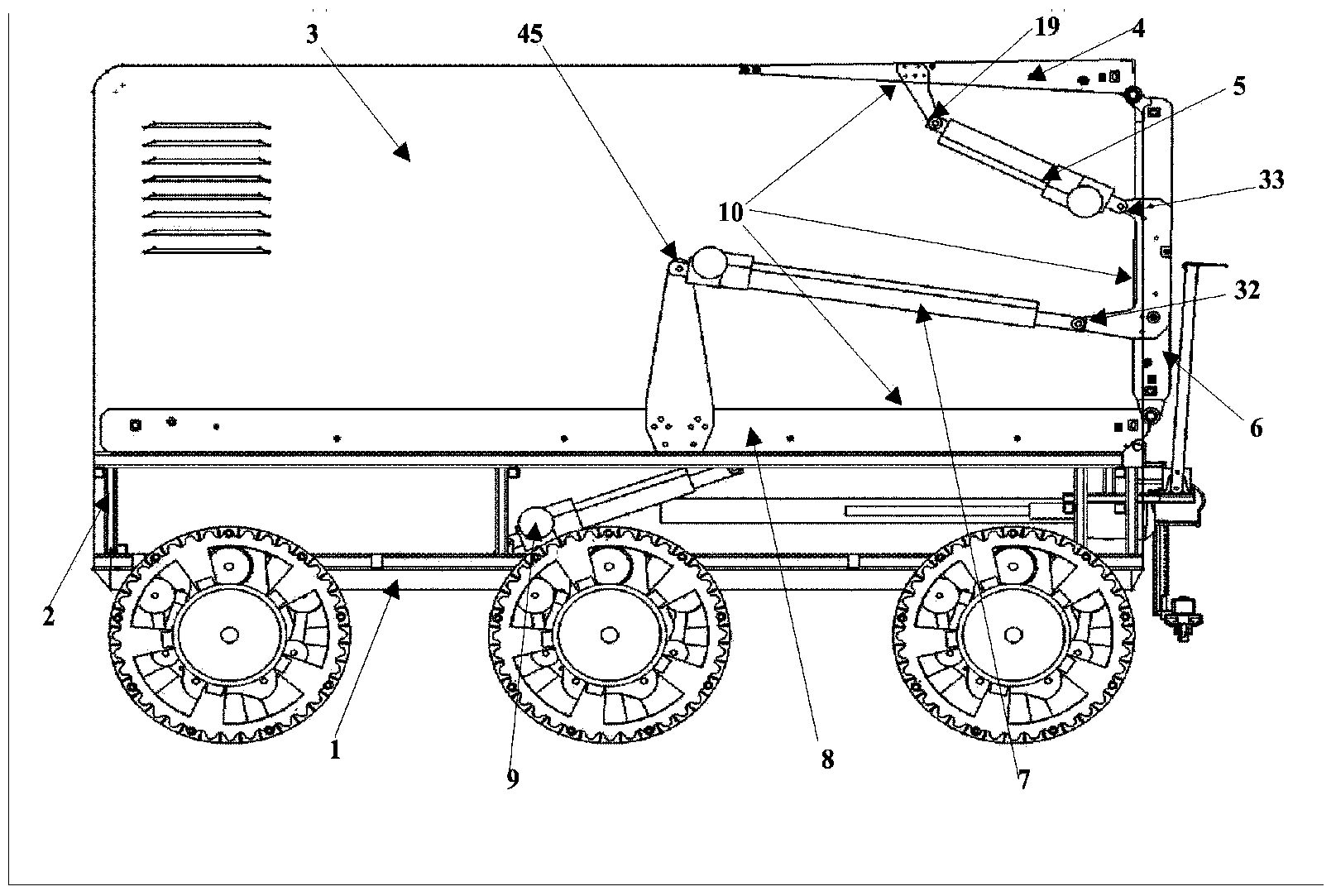
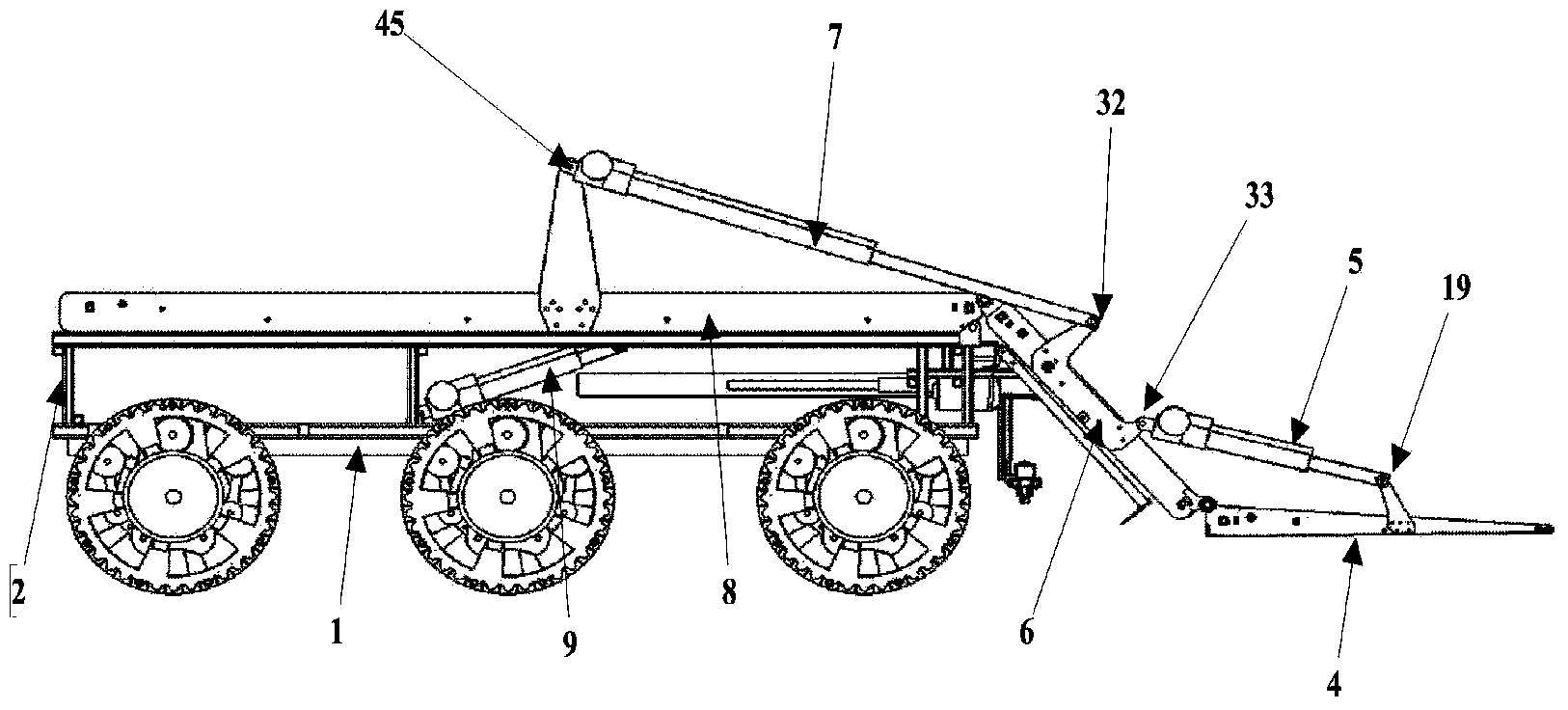
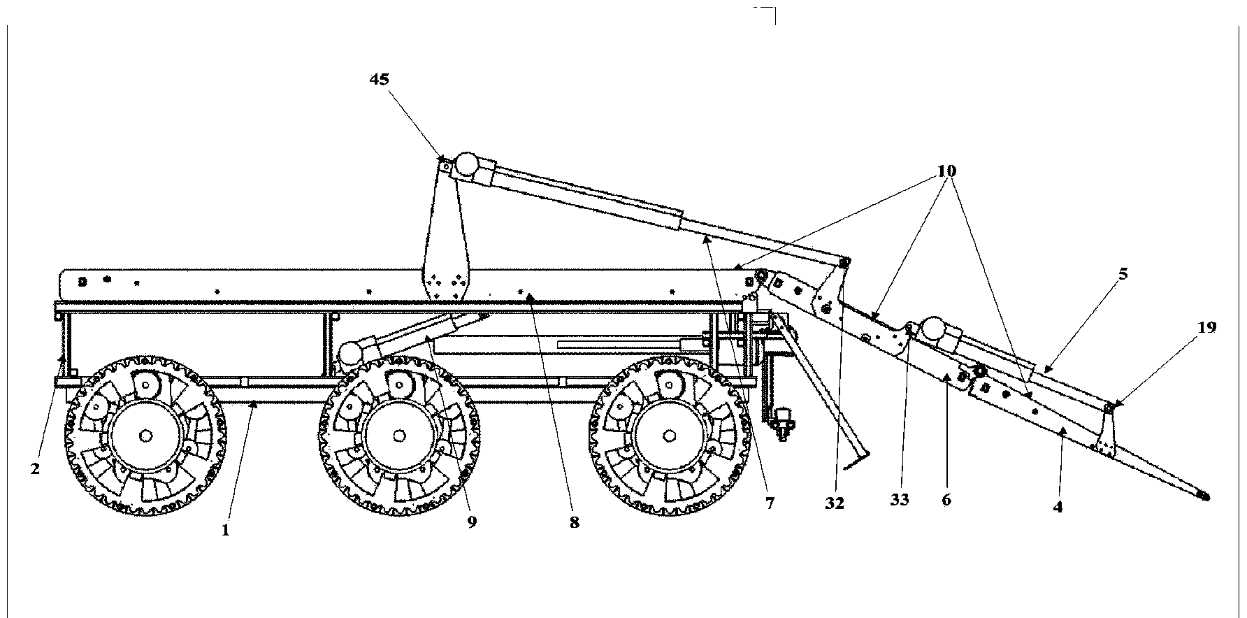
[0049] The complex environment robot rescue system of the present invention comprises a robot walking chassis 1, a vehicle frame 2, a robot shell 3, a storage system and an obstacle removal device 103 as an accessory system and a multifunctional executive arm system 104, composed of figure 1 — Figure 7 It can be seen that the storage system of the robot includes a personnel placement device ( Figure 7 ) and angle adjustment system (5, 5', 7, 7', 9).

[0050] One end of the long-distance electric push rod 7, 7' is hinged on the upper support 45 of the long-distance electric push rod, and the other end stretches when it receives the control signal. Therefore be hinged on the long-distance electric push rod 7,7 ' another end is hinged with the intermediate transition device 6 and rotates around the hinge shaft 47 on the personnel placement device 8. S...


PUM


Abstract

The invention relates to a robot rescue system used in a complicated environment. The robot rescue system comprises a personnel placement device (8), an intermediate transitional conveying device (6), a shovel-shaped picking device (4), an obstacle removing device and a multifunctional execution arm, wherein the personnel placement device (8), the intermediate transitional conveying device (6), the shovel-shaped picking device (4), the obstacle removing device and the multifunctional execution arm are arranged on a robot frame (2); the multifunctional execution arm comprises an arm main body fixedly connected with the robot frame (2) and an execution tail end (113) arranged at the tail end of the arm main body; each of the personnel placement device (8), the intermediate transitional conveying device (6) and the shovel-shaped picking device (4) is provided with a conveying belt (11) which is driven by an electric roller, can move in two directions and is used for transporting and moving wounded personnel. Obstacles around the wounded personnel and accessories on the body of the wounded personnel can be removed under the complicated and severe environment, the wounded personnel can be pulled to be away from the dangerous environment, and the trapped and critical wounded personnel can be transported and moved.

Description

technical field [0001] The invention belongs to the field of rescue robots, and in particular relates to a rescue system for picking up the disabled and injured in an unknown and complex environment. Background technique [0002] In recent years, with the occurrence of sudden natural disasters and major social security accidents, the surrounding natural and man-made environments are highly complex and arbitrary, their occurrence time is sudden, and the types of injuries caused by them are diverse. At present, the rescue and transportation of the wounded at large-scale disaster sites are mainly done manually and supplemented by machinery. Usually, medical staff and social rescue forces without professional medical knowledge work together to carry and move the trapped, critically injured, and postoperative wounded. [0003] The rescue work carried out by traditional manpower has the following problems in the rescue and treatment of the wounded: (1) The life safety of the resc...

Claims


Application Information

Patent Timeline
Patent Type & Authority Applications(China)
IPC IPC(8): B25J11/00B25J5/00B25J19/00B25J9/08
Inventor 侍才洪张西正陈炜李浩刘亚军李瑞欣苏卫华肖玉林崔克明郭月邢凯
Owner SANITARY EQUIP INST ACAD OF MILITARY MEDICAL SCI PLA
Why Eureka
Try Eureka