Smoke dust removal heat exchanger

A heat exchanger and dust collector technology, applied in the field of flue gas dust removal heat exchangers, can solve the problems of difficulty in disassembly, loss, sharp rise, and temperature continue to rise, so as to achieve simple and convenient maintenance and operation, reduce maintenance costs, and save manpower and material resources. Effect

Inactive Publication Date: 2015-02-18
黄秀琼
View PDF1 Cites 4 Cited by
  • Summary
  • Abstract
  • Description
  • Claims
  • Application Information

AI Technical Summary

Problems solved by technology

However, under abnormal circumstances, the heat exchanger is filled with stagnant water but the fire is still burning continuously. The water in the sheet at the first contact with the high-temperature flue gas will be vaporized, and the sheet at the first contact with the high-temperature flue gas will be vaporized. The temperature will rise sharply, and the temperature will continue to rise, which will destroy the connection mode between the heat exchanger plate groups. At this time, the safety protection device operates to close the gas valve, and water will flow out from the defect, causing heavy losses. In order to overcome the above defects, A plate heat exchanger for gas water heaters and gas heating water heaters has been developed. At present, a plate heat exchanger with a patent number of CN201420178095 has been disclosed in China. This design has solved some problems, but there are still other problems, such as smoke The air contains a lot of dust, and the heat exchanger body is difficult to disassemble. After a long time of use, the pipe is full of dust, which is difficult to clean and very inconvenient

Method used


Image

  • Smoke dust removal heat exchanger

Examples


Embodiment Construction

[0011] The technical solutions of the present invention will be further described below in conjunction with the accompanying drawings and through specific implementation methods.

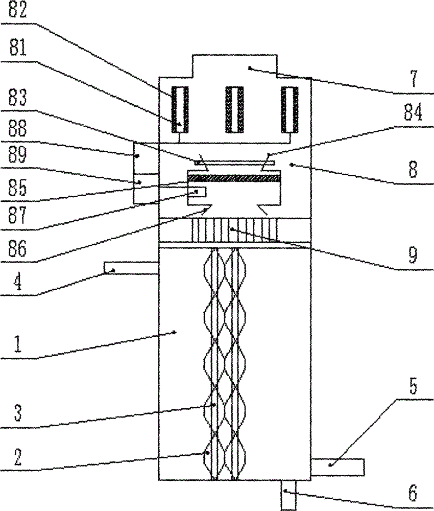
[0012] see figure 1 , in an embodiment of the present invention, a flue gas dedusting heat exchanger includes a body 1 of the heat exchanger, a flue gas channel 2, a water flow channel 3 and an ultrasonic dust removal device 8; wherein the upper left of the body 1 is provided with a cooling water outlet 4 , the lower right side of the main body 1 is provided with a cooling water inlet 5, and the bottom of the main body is provided with an air outlet 6, and the upper part of the main body 1 is connected to the ultrasonic dust removal device 8 through the air pipe 9, and the air pipe 9 is directly located directly below the dust removal outlet 86; the flue gas The channel 2 is a regular hexagon; the upper end of the water flow channel 3 is connected to the cooling water outlet 4, and the lower end is ...


PUM


Abstract

The invention discloses a smoke dust removal heat exchanger, which comprises a heat exchanger body, a smoke passage, a water flow passage and an ultrasonic dust removal device, wherein the ultrasonic dust removal device comprises an electric dust removal machine box and an ultrasonic dust remover, the ultrasonic dust remover is arranged in the electric dust removal machine box, a plurality of electrode plates, a plurality of dust collection nets, an air inlet, a high voltage power source and a rectifier are arranged in the electric dust removal machine box, multiple electrode plates are arranged at an inlet part near the air inlet, are parallelly arranged, and are arranged along the air flow direction of the air inlet, the dust collection nets are respectively arranged at the two side surfaces of each electrode plate, the air inlet is in a funnel shape with large opening diameter and large pipe diameter, high voltage power generated by the high voltage power source is rectified by the rectifier, and then is outputted to each electrode plate to supply power for the corresponding electrode plate, and the rectifier is connected with the ultrasonic dust removal device. The smoke dust removal heat exchanger has the advantages that the dust removal effect is good, the maintenance is convenient, and the labor is saved.

Description

technical field [0001] The invention relates to a heat exchanger, in particular to a flue gas dust removal heat exchanger. Background technique [0002] Plate heat exchanger is a kind of heat exchange equipment with high heat transfer efficiency, compact and light structure, large heat exchange area per unit volume and long service life. However, under abnormal circumstances, the heat exchanger is filled with stagnant water but the fire is still burning continuously. The water in the sheet at the first contact with the high-temperature flue gas will be vaporized, and the sheet at the first contact with the high-temperature flue gas will be vaporized. The temperature will rise sharply, and the temperature will continue to rise, which will destroy the connection mode between the heat exchanger plate groups. At this time, the safety protection device operates to close the gas valve, and water will flow out from the defect, causing heavy losses. In order to overcome the above de...

Claims


Application Information

Patent Timeline
Patent Type & Authority Applications(China)
IPC IPC(8): F23J15/06F23J15/02
CPCY02E20/30
Inventor 黄秀琼
Owner 黄秀琼
Why Eureka
Try Eureka