Conical laser intensity testing device and testing method

A test device and laser technology, applied in the field of optics, can solve problems such as large influence, difficult adjustment, long time-consuming, etc., and achieve the effect of improving test efficiency

Inactive Publication Date: 2015-02-18
XI'AN INST OF OPTICS & FINE MECHANICS - CHINESE ACAD OF SCI
View PDF7 Cites 0 Cited by
  • Summary
  • Abstract
  • Description
  • Claims
  • Application Information

AI Technical Summary

Problems solved by technology

For the first method, the cone-shaped laser is directly injected onto the probe, which is greatly affected by the angle of the incident laser; for the second method, the collimated laser is injected into the probe, and the adjustment is relatively difficult when testing this method. Difficult and time-consuming; for the third method, the laser is directly incident on the integrating sphere receiver, and this method is also greatly affected by the incident laser angle

Method used


Image

  • Conical laser intensity testing device and testing method

Examples


Embodiment Construction

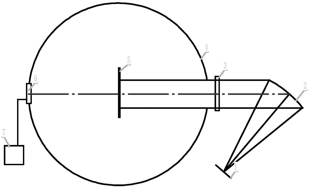
[0019] see figure 1 , including a fixed focus mask 1 , a collimating mirror 2 , an attenuation plate 3 , a scattering plate 5 , an integrating sphere receiver 4 , a power meter probe or an energy meter probe 6 and a display device 7 . The fixed focus cover 1 is arranged at the focal plane of the collimating mirror 2; the attenuating plate 3 and the diffusing plate 5 are successively arranged on the optical path where the reflected light formed after being reflected by the collimating mirror 2; the attenuating plate 3 and the diffusing plate 5 are respectively arranged on The outside and inside of the integrating sphere receiver 4; the power meter probe or the energy meter probe 6 is arranged on the side wall of the integrating sphere receiver 4; the display device 7 is connected with the power meter probe or the energy meter probe 6.

[0020] The fixed focus cover is provided with a small hole; the center of the small hole of the fixed focus cover coincides with the axial focu...


PUM


Abstract

Disclosed are a conical laser intensity testing device and testing method. The conical laser intensity testing device comprises a focus fixing cover, a collimating mirror, an attenuation plate, a scatter plate, an integrating sphere receiver, a power meter probe or energy meter probe and display equipment. The focus fixing cover is arranged on the focal plane of the collimating mirror. The attenuation plate and the scatter plate are sequentially arranged on a light path where reflected light reflected by the collimating mirror is located. The attenuation plate and the scatter plate are sequentially arranged outside and inside the integrating sphere receiver respectively. The power meter probe or energy meter probe is arranged on the side wall of the integrating sphere receiver. The display equipment is connected with the power meter probe or the energy meter probe. The conical laser intensity testing device and testing method are high in testing precision.

Description

technical field [0001] The invention belongs to the field of optics, and relates to a laser light intensity measuring device and a testing method, in particular to a light intensity measuring device and a testing method of a conical laser light path. Background technique [0002] Lasers are widely used in national defense, aerospace, scientific research and other fields. In the laser light path, it is usually necessary to monitor and measure the light intensity information of the laser. At present, the mainstream equipment for testing laser intensity is mainly a power meter (energy meter). [0003] Usually a power meter (energy meter) generally consists of a probe and a display device. When a power meter (energy meter) tests a parallel laser beam, it usually has a high test accuracy, but when it tests a conical laser beam, the test result usually deviates greatly due to the influence of the angle. At present, when testing the cone laser, three methods are usually used: the...

Claims


Application Information

Patent Timeline
Patent Type & Authority Applications(China)
IPC IPC(8): G01J1/00G01J1/04
Inventor 陈永权段亚轩李坤赵建科赛建刚胡丹丹薛勋潘亮聂申
Owner XI'AN INST OF OPTICS & FINE MECHANICS - CHINESE ACAD OF SCI
Why Eureka
Try Eureka