
Piezoresistive MEMS high-range acceleration sensor with no lead and manufacturing method thereof

An acceleration sensor, piezoresistive technology, applied in the piezoresistive MEMS high-range acceleration sensor and its manufacturing field, can solve the problems such as the limited application range of the piezoresistive high-range acceleration sensor, so as to solve the problem of limited application range and avoid The effect of circuit failure and widening the scope of application

Active Publication Date: 2015-02-18
ZHONGBEI UNIV
View PDF5 Cites 8 Cited by
  • Summary
  • Abstract
  • Description
  • Claims
  • Application Information

AI Technical Summary

Problems solved by technology

[0003] In order to solve the problem that the applicable range of the existing piezoresistive high-range acceleration sensor is limited, the present invention provides a leadless piezoresistive MEMS high-range acceleration sensor and its manufacturing method

Method used


Image

  • Piezoresistive MEMS high-range acceleration sensor with no lead and manufacturing method thereof
  • Piezoresistive MEMS high-range acceleration sensor with no lead and manufacturing method thereof
  • Piezoresistive MEMS high-range acceleration sensor with no lead and manufacturing method thereof

Examples


Embodiment Construction

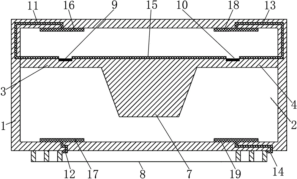
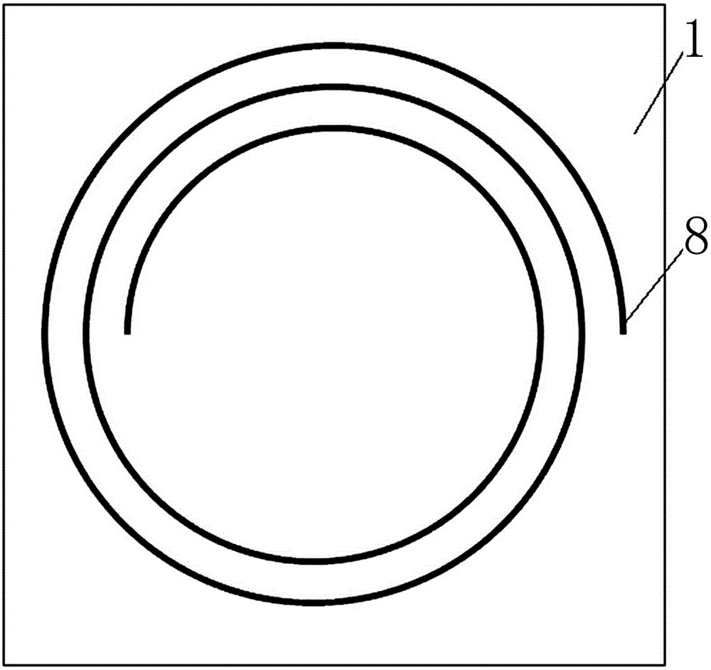
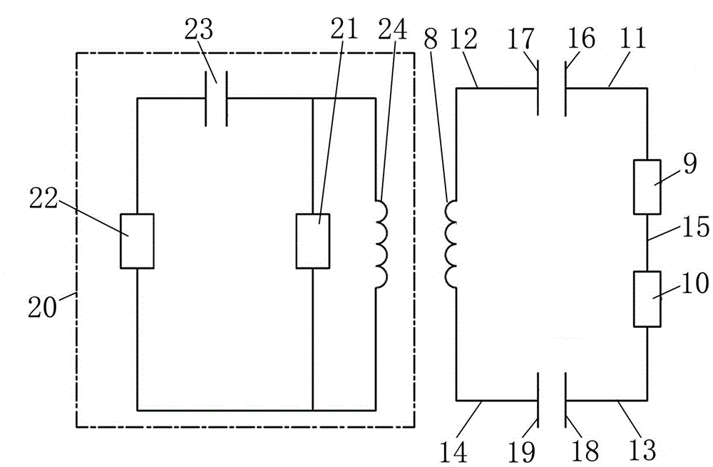
[0027] A leadless piezoresistive MEMS high-range acceleration sensor, including a substrate 1, a closed cavity 2, a first cantilever beam 3, a second cantilever beam 4, a third cantilever beam 5, a fourth cantilever beam 6, a mass block 7, Planar spiral inductor 8, first varistor 9, second varistor 10, first capacitor, second capacitor, first wire hole, second wire hole, third wire hole, fourth wire hole, first electrical connection 11. The second electrical connection 12, the third electrical connection 13, the fourth electrical connection 14, the fifth electrical connection 15;

[0028] Wherein, the substrate 1 is formed by bonding an upper substrate, a middle substrate, and a lower substrate;

[0029] The closed cavity 2 is arranged inside the substrate 1;

[0030]The left end face of the first cantilever beam 3 is fixed with the left inner cavity wall of the closed cavity 2; the right end face of the second cantilever beam 4 is fixed with the right inner cavity wall of th...


PUM


Abstract

The invention relates to an acceleration sensor, in particular to a piezoresistive MEMS high-range acceleration sensor with no lead and a manufacturing method of the piezoresistive MEMS high-range acceleration sensor with no lead. The piezoresistive MEMS high-range acceleration sensor with no lead and the manufacturing method of the piezoresistive MEMS high-range acceleration sensor with no lead solve the problem that the application range of an existing piezoresistive MEMS high-range acceleration sensor is limited. The piezoresistive MEMS high-range acceleration sensor with no lead comprises a substrate, a closed cavity, a first cantilever beam, a second cantilever beam, a third cantilever beam, a fourth cantilever beam, a mass block, a planar spiral inductor, a first piezoresistor, a second piezoresistor, a first capacitor, a second capacitor, a first wire hole, a second wire hole, a third wire hole, a fourth wire hole, a first electric connecting wire, a second electric connecting wire, a third electric connecting wire, a fourth electric connecting wire and a fifth electric connecting wire. The piezoresistive MEMS high-range acceleration sensor with no lead is suitable of acceleration measurement.

Description

technical field [0001] The invention relates to an acceleration sensor, in particular to a leadless piezoresistive MEMS high-range acceleration sensor and a manufacturing method thereof. Background technique [0002] The piezoresistive high-range acceleration sensor has gradually become one of the hotspots in the field of acceleration sensor research because of its high sensitivity, strong overload capacity, and good adaptability to harsh working environments (such as high temperature, radiation, and high impact, etc.). Under the existing technical conditions, piezoresistive high-range acceleration sensors all have lead wires, so that their measurement methods are limited to contact measurement, which severely limits their scope of application. Specifically, in some harsh environments (such as high temperature, high pressure, high impact, etc.), contact measurement can easily cause problems such as circuit failure and high-temperature degradation of leads, which leads to the...

Claims


Application Information

Patent Timeline
Patent Type & Authority Applications(China)
IPC IPC(8): G01P15/12B81B7/02B81C1/00
Inventor 石云波刘俊唐军马宗敏陈艳香李祥李策智丹
Owner ZHONGBEI UNIV
Learn More