Metering and calibrating method and metering and calibrating device for sound source identifying and positioning system

A positioning system and sound source identification technology, applied in the field of positioning, can solve the problems of verification and use units, and achieve the effect of efficient measurement

Active Publication Date: 2015-02-18
ZHEJIANG MEASUREMENT SCI RES INST
View PDF4 Cites 9 Cited by
  • Summary
  • Abstract
  • Description
  • Claims
  • Application Information

AI Technical Summary

Problems solved by technology

[0004] So far, there are no relevant standards and norms at home and abroad to measure the technical indicators and accuracy of the sound source identification and positioning system, which has caused great trouble to the verification of the metrology department and the user unit

Method used


Image

  • Metering and calibrating method and metering and calibrating device for sound source identifying and positioning system
  • Metering and calibrating method and metering and calibrating device for sound source identifying and positioning system
  • Metering and calibrating method and metering and calibrating device for sound source identifying and positioning system

Examples


Embodiment 1

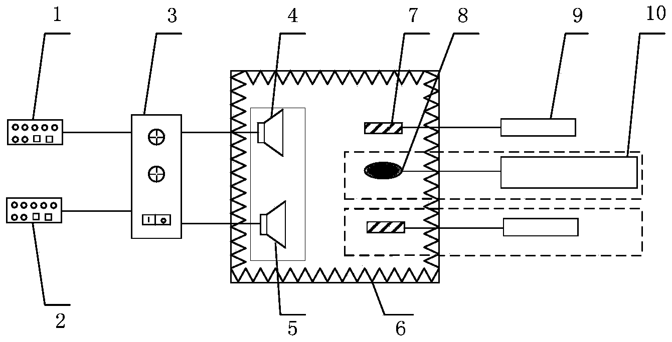
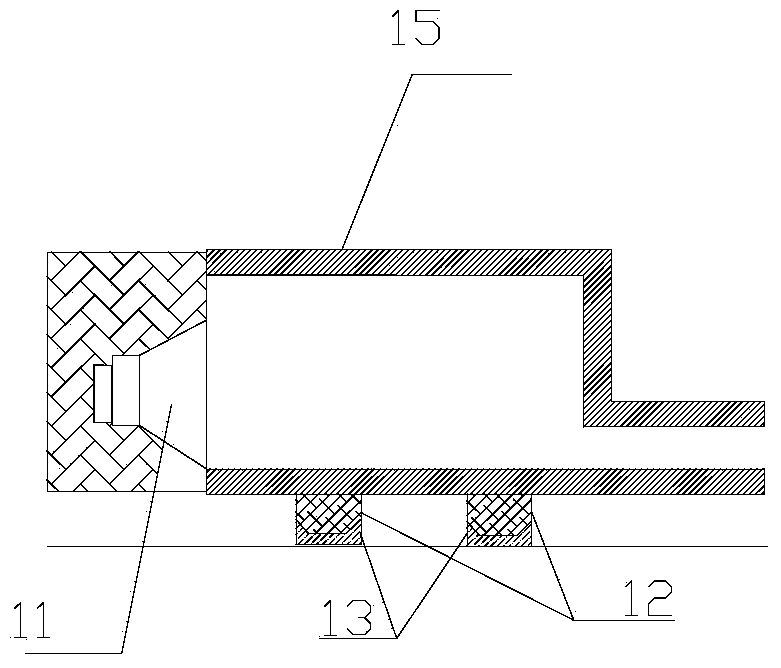
[0030] Such as figure 1 As shown, the outputs of the audio signal generators 1 and 2 are respectively connected to the two input ends of the power amplifier 3, and the two outputs of the power amplifier 3 are respectively connected to the standard sound sources 4 and 5. Standard point sound source selection Figure 4 The shown tapered cross-section waveguide standard point sound source composed of the loudspeaker 11 and the tapered cross-section waveguide airtight casing 14 is selected Figure 6 The standard sound source system of the tapered cross-section waveguide is shown, and the lateral spatial resolution of the sound source identification and positioning system (beamforming method) is measured and calibrated in the full anechoic chamber 6.

[0031] The measurement frequency points are selected according to 1 / 3 octave. For the measurement frequency point of 1000 Hz, the working standard microphone 7 is arranged 1 m directly in front of the standard sound source 4 . pas...

Embodiment 2

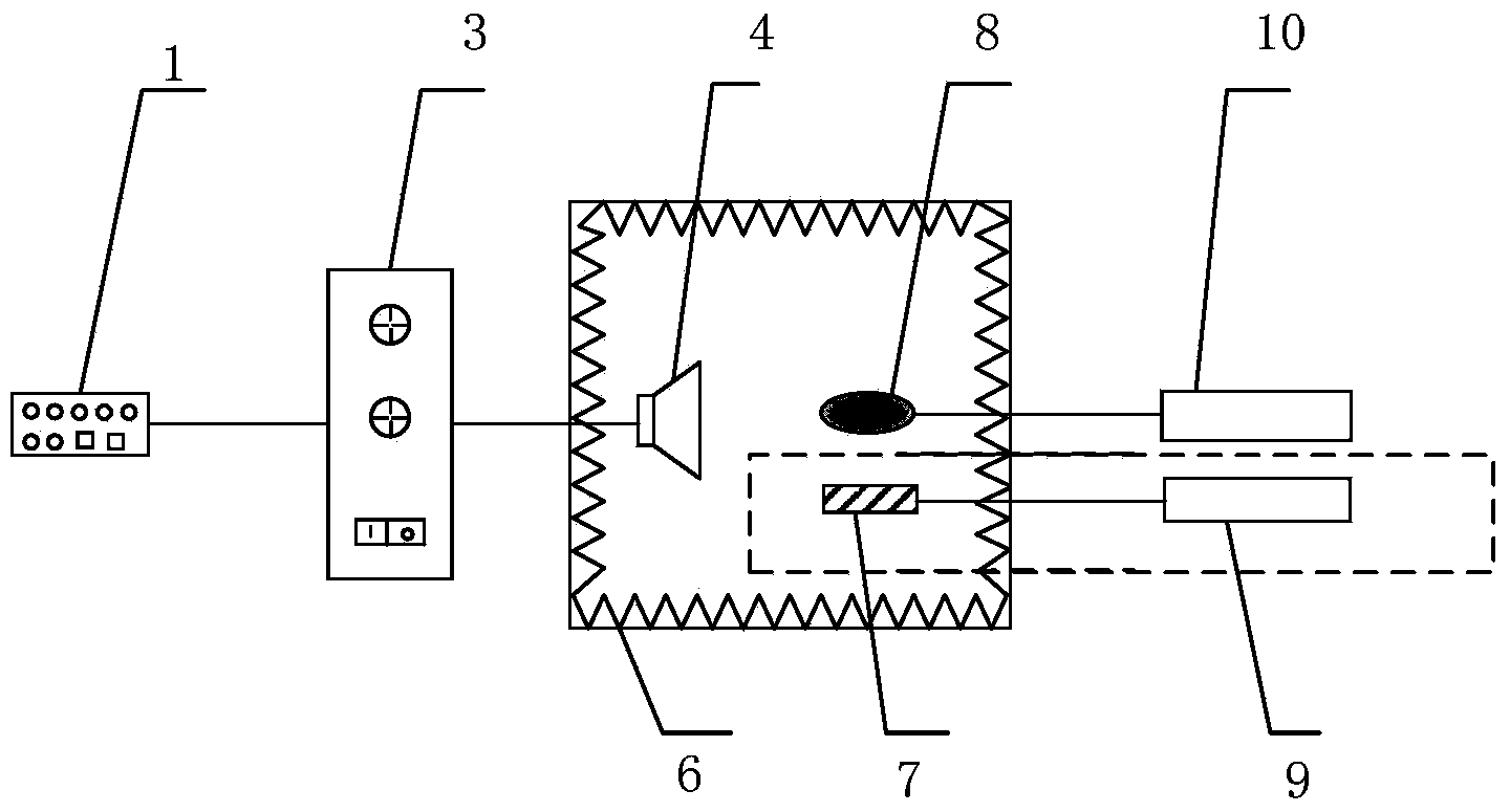
[0039] Such as figure 2 As shown, the output of the audio signal generator 1 is connected to the input of the power amplifier 3, and the output of the power amplifier 3 is connected to the standard sound source 4. Standard point sound source selection image 3 The shown abrupt cross-section waveguide standard point sound source composed of the loudspeaker 11 and the abrupt cross-section waveguide airtight casing 15 is selected Figure 5 The shown waveguide standard sound source system with abrupt cross-section is used to measure and calibrate the main-side lobe suppression ratio of the sound source identification and positioning system (beamforming method) in the full anechoic chamber 6.

[0040] Arrange the working standard microphone 7 1m in front of the standard sound source 4, set the frequency of the sinusoidal signal output by the audio signal generator 1 to 1000 Hz, and adjust the output voltage amplitude U1 so that the sound pressure level at the standard microphone ...


PUM


Abstract

The invention relates to a metering and calibrating method and a metering and calibrating device for a sound source identifying and positioning system. A two-point sound source sounding method is adopted for calibrating transverse spatial resolution of the sound source identifying and positioning system (a beam forming method), and a single-point sound source sounding method is adopted for calibrating a main lobe suppression ratio and a side lobe suppression ratio of the sound source identifying and positioning system, so that the sound source identifying and positioning system can be metered and calibrated precisely. According to the metering and calibrating device, a variable cross-section waveguide tube scheme is adopted for realizing approximate point sound sources, linear guide rails and corresponding slide block structures are adopted, and an upper computer controls motor drive to achieve precise change of the distances of the point sound sources. The metering and calibrating method and the metering and calibrating device achieve accurate and efficient metering of the sound source identifying and positioning system and provide a reference mode for metering and calibrating the sound source identifying and positioning system.

Description

technical field [0001] The invention relates to a measurement and calibration method and a standard device, in particular to a measurement and calibration method and a standard device for a sound source identification and positioning system (beam forming method), and belongs to the field of positioning technology. Background technique [0002] The sound source identification and positioning system is widely used in fields that have certain requirements for noise indicators. At present, its application fields include: development and production of high-speed rail, automobiles, forklifts, high-end ships, ships, submarines, and aircraft; steam engines, diesel engines, Manufacture of compressors and special equipment, manufacture and use of belt conveyors; production of air conditioners, refrigerators, televisions, washing machines, shavers and other home appliances; manufacture of computer systems and parts, and research and production of various other mechanical equipment. Esp...

Claims


Application Information

Patent Timeline
Patent Type & Authority Applications(China)
IPC IPC(8): G01S5/18
CPCG01S5/18
Inventor 姚磊桑帅军张志凯孙旭朋陈杭升
Owner ZHEJIANG MEASUREMENT SCI RES INST
Why Eureka
Try Eureka