LabVIEW-based (laboratory virtual instrumentation engineering workbench based) microphone array sound source localization method and device

A microphone array and sound source localization technology, applied in the field of localization, can solve difficult problems and achieve the effects of reducing model errors, improving accuracy, and improving real-time performance

Inactive Publication Date: 2015-02-18
HEBEI UNIV OF TECH
View PDF4 Cites 33 Cited by
  • Summary
  • Abstract
  • Description
  • Claims
  • Application Information

AI Technical Summary

Problems solved by technology

However, the speech signal and noise signal received by a microphone usually overlap each other in time and spectrum, so it is necessary to separate

Method used


Image

  • LabVIEW-based (laboratory virtual instrumentation engineering workbench based) microphone array sound source localization method and device
  • LabVIEW-based (laboratory virtual instrumentation engineering workbench based) microphone array sound source localization method and device
  • LabVIEW-based (laboratory virtual instrumentation engineering workbench based) microphone array sound source localization method and device

Examples


Embodiment 1

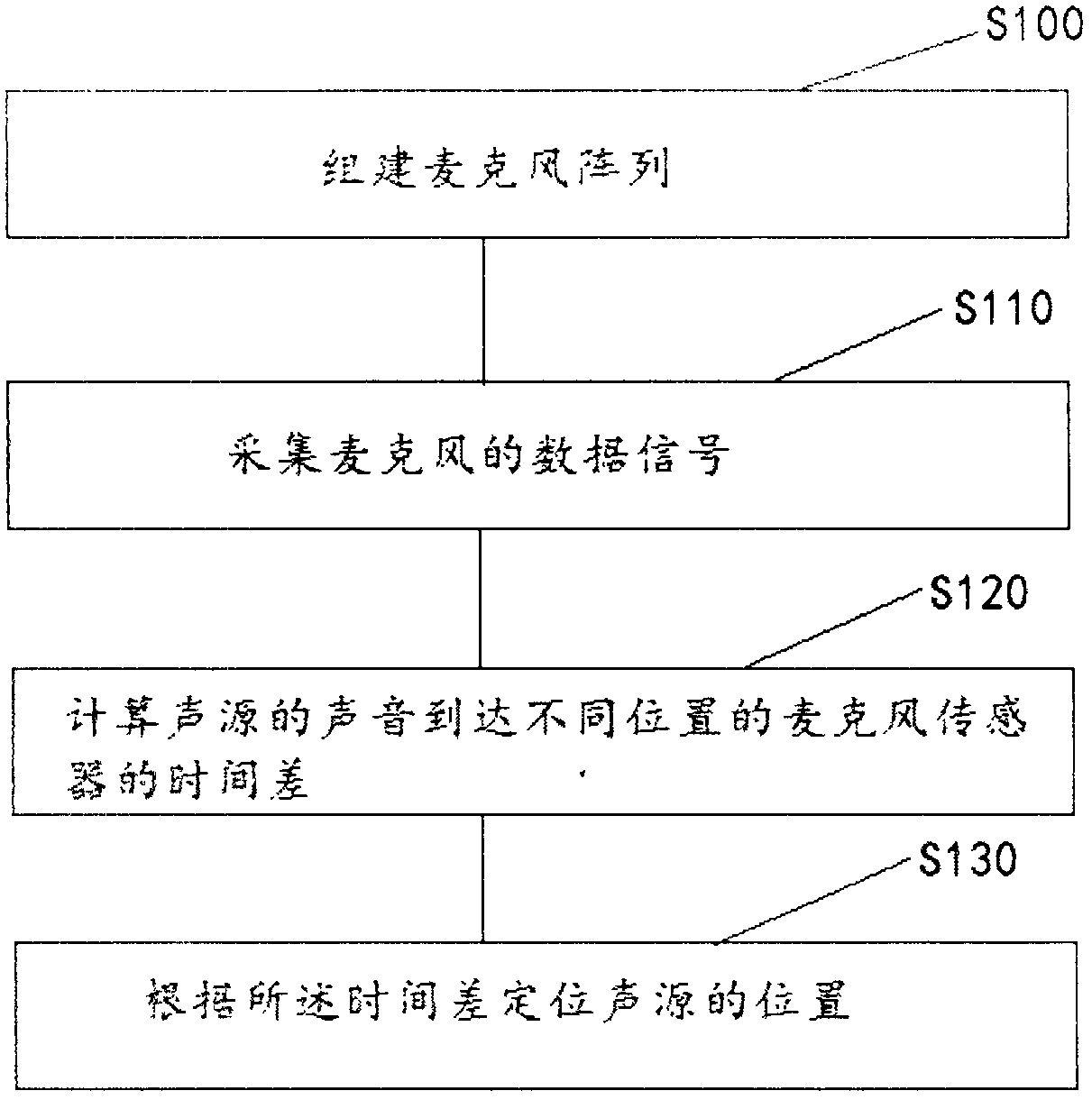
[0032] Such as figure 1 As shown, the microphone array sound source localization method based on LabVIEW includes the following steps:

[0033] Step S100: building a microphone array;

[0034] Step S110: collecting the data signal of the microphone;

[0035] Step S120: Calculate the time difference between the sound of the sound source reaching the microphone sensors at different positions;

[0036] Step S130: Locate the position of the sound source according to the time difference.

[0037] In this embodiment, the microphone array is used to realize the three-dimensional spatial positioning of the sound source, which improves the accuracy of the sound source positioning, effectively suppresses the interference of uninteresting sounds such as noise, and calculates the time difference between the sound of the sound source arriving at the microphone sensor at different positions, reducing The complexity of the algorithm is reduced, and the real-time performance of the pickup ...

Embodiment 2

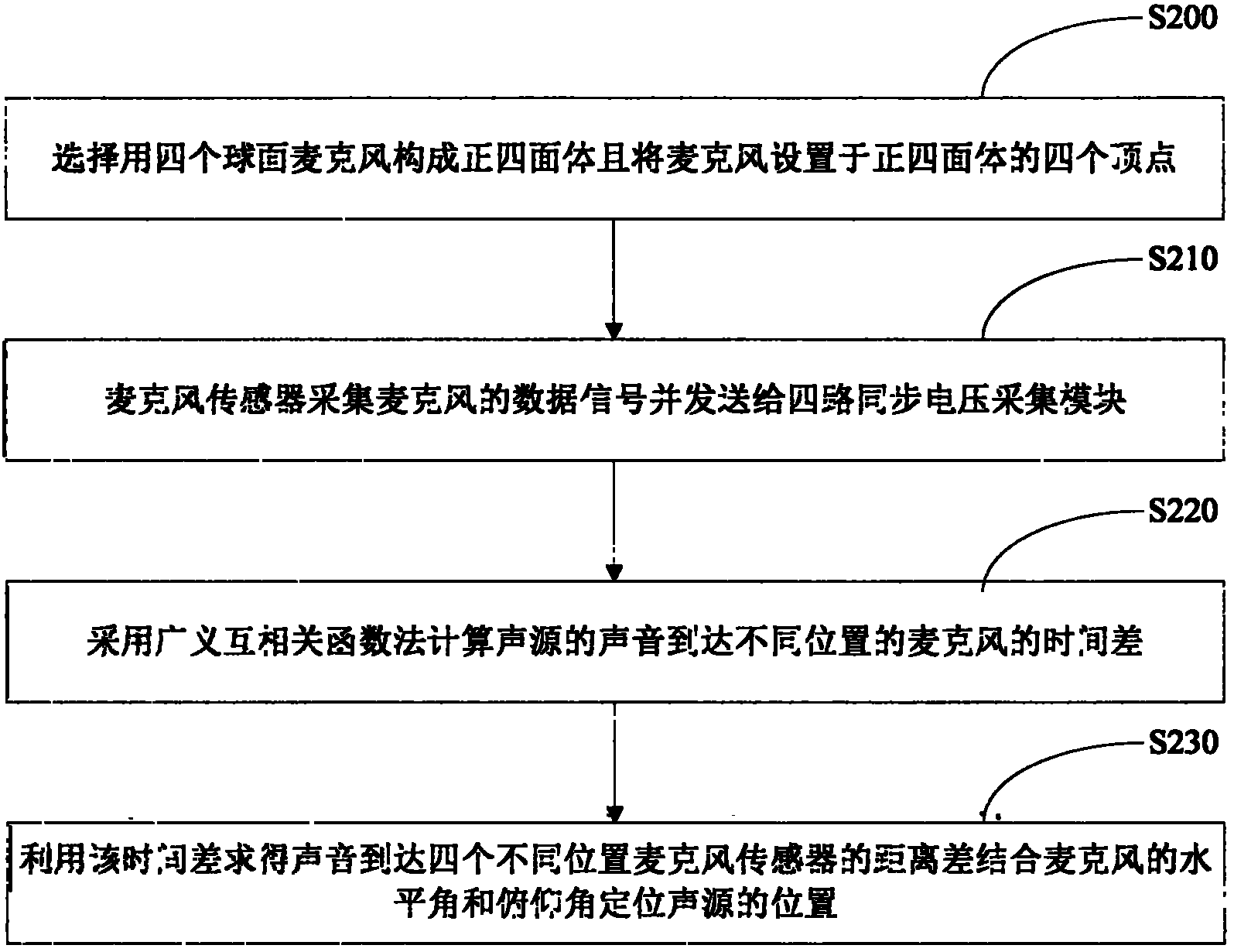
[0039] Such as figure 2 As shown, the microphone array sound source localization method based on LabVIEW includes the following steps:

[0040] Step S200: Choose to use four spherical microphones to form a regular tetrahedron and set the microphones on the four vertices of the regular tetrahedron, microphone m 0 1. Microphone m 1 2. Microphone m 2 3 and microphone m 3 4 is the position of the four spherical microphones in the space model, and the space Cartesian coordinate system is established with the circumcircle center of the tetrahedron formed by the four spherical microphones as the coordinate origin 0. m 0 On the positive half of the z-axis, m 1 、m 2 and m 3 are all below the origin, m 1 Projection on the plane xOy on the positive x-axis, m 2 and m 3 The connecting line is parallel to the y-axis. Then the coordinates of the four microphones in the three-dimensional space model are: m 2 ( - ...

Embodiment 3

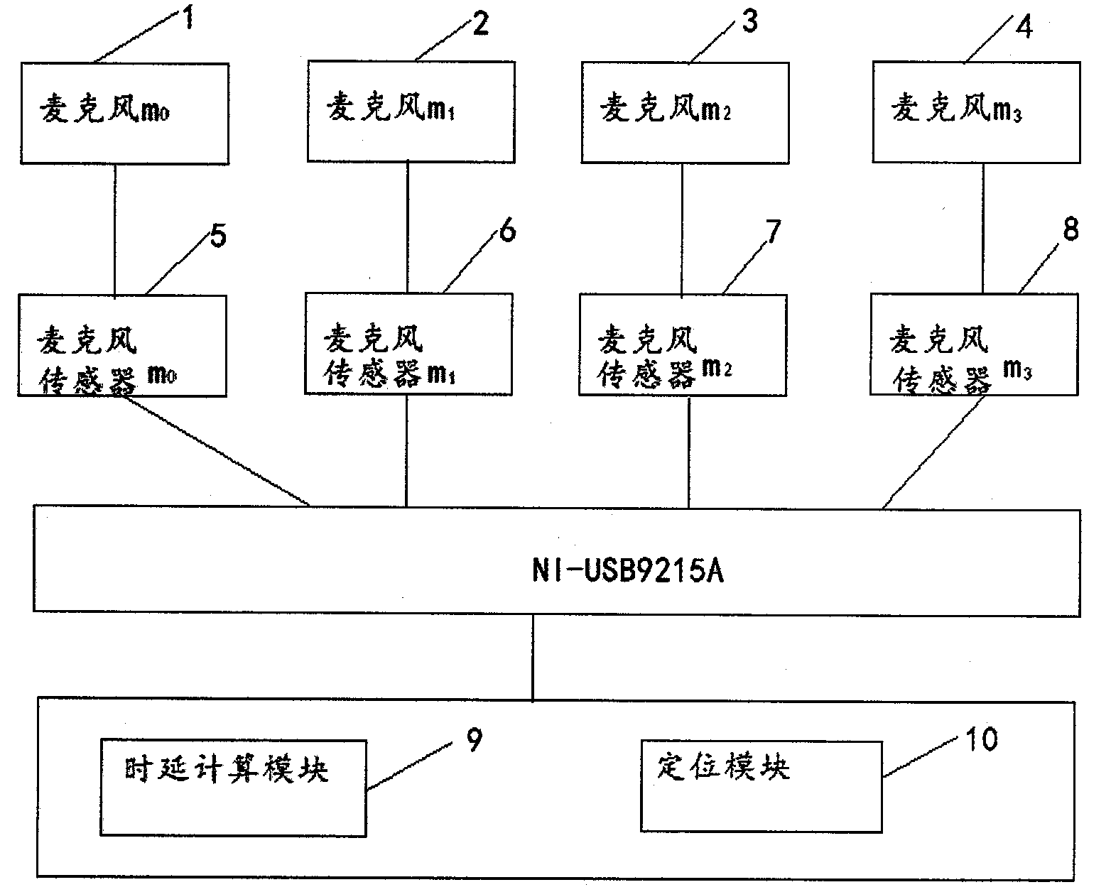
[0079] Such as Figure 4 Shown, the microphone array sound source localization device based on LabVIEW, including:

[0080] The building module is used to build a microphone array; the building module includes four spherical microphones, and the four spherical microphones form a regular tetrahedron and the microphones are arranged on the four vertices of the regular tetrahedron, and the geometric center of the regular tetrahedron is a three-dimensional coordinate The origin of the system and one of the microphones is located on the positive half axis of the Z axis;

[0081] The acquisition module is used to collect the data signal of the microphone; the acquisition module includes a microphone sensor and four synchronous voltage acquisition modules, and the data signal collected by the microphone sensor is input into the four synchronous voltage acquisition module in the form of an analog voltage signal; the four synchronous voltage The acquisition module is NI USB-9215A;

...


PUM


Abstract

The invention discloses a LabVIEW-based (laboratory virtual instrumentation engineering workbench based) microphone array sound source localization method and device. The method includes the steps of building a microphone array; acquiring microphone data signals; calculating differences of time which sound of a sound source takes to reach to microphone sensors at different positions; localizing the sound source according to the differences of time. The method and the device have the advantages that three-dimensional spatial localization of sound sources is achieved by the use of a microphone array, sound source localization precision is improved, interference of uninterested sounds such as noise is effectively inhibited, the differences of time which the sound of the sound source takes to reach to the microphone sensors at the different positions are calculated, calculation complexity is reduced, and timeliness of a pickup system is improved.

Description

technical field [0001] The invention relates to a localization method, in particular to a microphone array sound source localization method and device based on LabVIEW. Background technique [0002] In the microphone-based sound pickup system, the sound source localization technology can determine the sound of interest, so that the sound pickup system can perform sound denoising, sound source tracking, speech extraction and separation, etc. on the received signal. Accurate sound source localization can effectively improve the quality of voice communication in noisy backgrounds. [0003] Traditional sound pickup tools are generally a single isolated microphone. A single microphone will receive all sounds including noise within its pickup range, that is, the signal received by a single microphone is a mixed signal composed of environmental noise and sounds from multiple sound sources. [0004] A single microphone cannot adaptively align and track the speaker of interest, and...

Claims


Application Information

Patent Timeline
IPC IPC(8): G01S5/22
CPCG01S5/22
Inventor 杨鹏李立鹏孙昊徐勤奇王春絮韩思思
Owner HEBEI UNIV OF TECH
Why Eureka
Try Eureka