S-frequency-band monopulse self-tracking antenna system

An antenna system, monopulse technology, applied in the direction of antennas, electrical components, etc., can solve the problems of complex feeder network, design time and poor performance, difficulty in achieving circular polarization processing, etc., to achieve good performance and reliability The effect of electrical performance and simple structure

Inactive Publication Date: 2015-02-18
CHENGDU JINJIANG ELECTRONICS SYST ENG
View PDF2 Cites 4 Cited by
  • Summary
  • Abstract
  • Description
  • Claims
  • Application Information

AI Technical Summary

Problems solved by technology

[0003] The earliest monopulse tracking radar used the horn feed. It added the received signals of four horns to form a sum signal. The difference between the left and right pairs of horns formed an azimuth difference signal, and the difference between the upper and lower pairs of horns formed a pitch difference signal. The sum and difference of the horn feed are contradictory, and the design time and poor performance cannot be optimized, so the design

Method used


Image

  • S-frequency-band monopulse self-tracking antenna system
  • S-frequency-band monopulse self-tracking antenna system
  • S-frequency-band monopulse self-tracking antenna system

Examples


Embodiment Construction

[0035] The technical solution of the present invention will be further described in detail below in conjunction with the accompanying drawings, but the protection scope of the present invention is not limited to the following description.

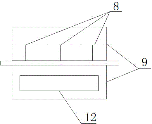
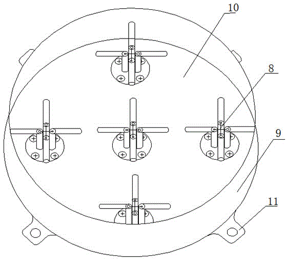
[0036] Such as figure 1 As shown, the S-band monopulse self-tracking antenna system includes an antenna, a feed system and an antenna feed box 9, and the feed system includes an antenna feed source and a beamforming network 12, and the antenna feed box 9 There are two layers of structure, the upper and lower layers are separated by the base plate 10, the upper layer is used to install the antenna feed, and the lower layer is used to install the beam forming network 12.

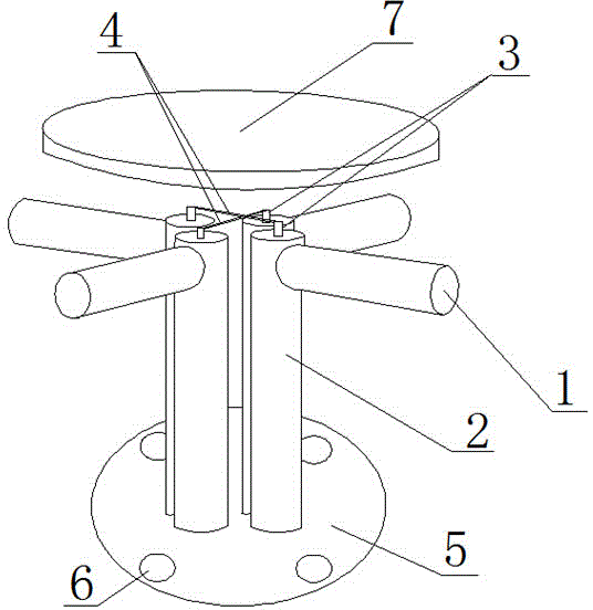
[0037] The antenna feed source includes five cross oscillators 8 arranged in a rhombus distribution structure, one of which is the central oscillator unit and is arranged on the diagonal intersection of the rhombus, and the other four cross oscillators 8 are the outer The ...


PUM


Abstract

The invention discloses an S-frequency-band monopulse self-tracking antenna system which comprises an antenna and a feed source system. The feed source system comprises an antenna feed source and a beam forming network (12). The antenna feed source comprises five crossed vibrators (8) which are arranged in a rhombus distribution structure. One crossed vibrator (8) is a central vibrator unit arranged on the point of intersection of diagonal lines of the rhombus. The other four crossed vibrators (8) are outside vibrator units which are arranged on the four vertexes of the rhombus respectively. The five crossed vibrators (8) receive signals. The beam forming network (12) comprises a sum signal forming circuit and a difference signal forming circuit. The sum signal forming circuit is connected with the central vibrator unit. The difference signal forming circuit is connected with the outside vibrator units. According to the S-frequency-band monopulse self-tracking antenna system, the central vibrator unit receives a formed sum signal, the outside vibrator units receive formed difference signals, and therefore monopulse self-tracking is achieved.

Description

technical field [0001] The invention relates to the field of antenna systems, in particular to an S-band monopulse self-tracking antenna system. Background technique [0002] In order to realize the self-tracking of space flight targets by using single-channel monopulse tracking, the monopulse tracking antenna system is an important part of monopulse tracking radar, and the received signal is formed by the beamforming network and the difference signal. The performance of the monopulse antenna depends largely on the feed source of the antenna. [0003] The earliest monopulse tracking radar used the horn feed. It added the received signals of the four horns to form a sum signal. The difference between the left and right pairs of horns formed an azimuth difference signal, and the difference between the upper and lower pairs of horns formed a pitch difference signal. The sum and difference of the horn feed are contradictory, and the design and poor performance cannot be optimiz...

Claims


Application Information

Patent Timeline
IPC IPC(8): H01Q3/26
Inventor 乔益民郑蜀晔霍建忠
Owner CHENGDU JINJIANG ELECTRONICS SYST ENG
Why Eureka
Try Eureka