A Claw Pole Motor Rotor Structure Using Powdered Iron Core Material Efficiently to Reduce Iron Loss

A powder core and rotor technology, applied in the direction of magnetic circuit shape/style/structure, electrical components, electromechanical devices, etc., can solve the problems of uncontrolled motor rotor magnetic field, weakened slotting effect, increased processing difficulty, etc., to achieve guaranteed Performance, usage reduction, and upgrade cost reduction effects

Active Publication Date: 2017-10-10
SHANGHAI VALEO AUTOMOTIVE ELECTRICAL SYST
View PDF2 Cites 0 Cited by
  • Summary
  • Abstract
  • Description
  • Claims
  • Application Information

AI Technical Summary

Problems solved by technology

The disadvantages of this technical solution are: first, adding magnetic steel in the slot will cause the magnetic field of the motor rotor to be uncontrolled. The reason is that in the application of the generator, even if the motor is expected to idle without generating power, the magnets of the rotor will still work. resulting in unnecessary losses
Second, arranging the coils in the slot obviously greatly increases the difficulty of processing
Third, at the same time, the coil as a metal material will also produce serious eddy current loss, which will weaken or even cancel the slotting effect
Although the dust core can guarantee the rigidity, its strength may not meet the huge centrifugal force in the rotor that needs to rotate at high speed

Method used


Image

  • A Claw Pole Motor Rotor Structure Using Powdered Iron Core Material Efficiently to Reduce Iron Loss
  • A Claw Pole Motor Rotor Structure Using Powdered Iron Core Material Efficiently to Reduce Iron Loss
  • A Claw Pole Motor Rotor Structure Using Powdered Iron Core Material Efficiently to Reduce Iron Loss

Examples


Embodiment Construction

[0023] A rotor for an alternator according to a specific embodiment of the present invention will be described in detail below with reference to the accompanying drawings. However, the present invention should be understood as not limited to such embodiments described below, and the technical idea of ​​the present invention can be implemented in combination with other known technologies or other technologies having the same functions as those known technologies.

[0024] In the following description, in order to clearly show the structure and working method of the present invention, many directional words will be used to describe, but "front", "rear", "left", "right", "outer", "inner" should be used Words such as ", "outward", "inward", "upper" and "lower" are to be understood as convenient terms, and should not be understood as restrictive terms.

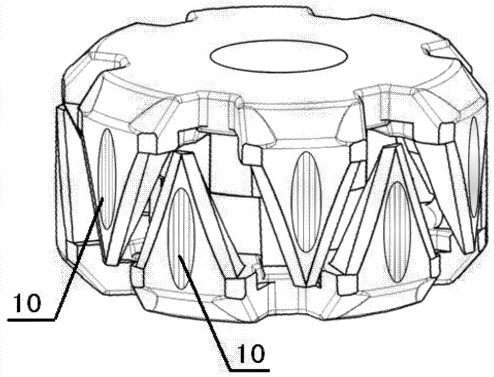
[0025] The object of the present invention is to provide a claw-pole motor rotor that can effectively reduce iron loss, facilitat...


PUM


Abstract

The invention discloses a rotor used for an alternating-current power generator, and particularly relates to a claw pole motor rotor structure efficiently utilizing a compressed-powder iron core material to lower iron loss. The rotor comprises a claw pole and a rotating shaft, the claw pole comprises a plurality of pole teeth, the claw pole is fixed to the rotating shaft, and a compressed-powder iron core layer covers the surface of at least one pole tooth of the claw pole partly or fully.

Description

technical field [0001] The invention relates to a motor rotor, in particular to a rotor for a claw pole structure motor. Background technique [0002] The motor with claw pole structure is widely used in the automotive field because of its firm structure, low production cost and convenient output power adjustment. As the requirements for production efficiency and environmental protection have become higher and higher in recent years, the corresponding requirements for the efficiency and volume of automotive motors have also increased. [0003] Due to the limitation of the structure and strength of the claw pole motor, the rotor part cannot adopt the stacked structure of silicon steel sheets like the stator, but can only adopt a solid structure, which is processed by casting and turning and milling. Compared with other types of motors, the iron loss of the claw pole structure motor is particularly prominent. Iron loss is a general term for hysteresis loss, eddy current loss...

Claims


Application Information

Patent Timeline
Patent Type & Authority Patents(China)
IPC IPC(8): H02K1/22
CPCH02K1/243H02K1/28
Inventor 孙韬张守佳徐晓晔
Owner SHANGHAI VALEO AUTOMOTIVE ELECTRICAL SYST
Why Eureka
Try Eureka