electrode probe

A probe and electrode technology, applied in the field of electrode probes, can solve the problems of insufficient prevention of thrombus, poor thrombus formation inhibition effect due to electrode surface cooling effect, and small front-end electrode, and achieve excellent thrombosis inhibition effect and thrombosis inhibition effect. Excellent effect, thrombus formation inhibitory effect

Active Publication Date: 2017-04-05
JAPAN LIFELINE CO LTD
View PDF9 Cites 0 Cited by
  • Summary
  • Abstract
  • Description
  • Claims
  • Application Information

AI Technical Summary

Problems solved by technology

In addition, when cauterizing is performed with the tip electrode formed with such an edge, the current density at the edge portion becomes extremely high, and there is a possibility that an abnormal temperature rise occurs in this portion, and a thrombus may form rapidly.
[0008] (2) Even if physiological saline is sprayed from the opening formed on the surface of the front-end electrode, the surface of the front-end electrode cannot be sufficiently rinsed (covered with liquid), therefore, the surface of the front-end electrode cannot be sufficiently cooled, and in addition, the surface of the front-end electrode cannot be sufficiently cooled. effectively prevent / inhibit the formation of thrombus on the surface
In particular, in the probes described in Patent Document 1 and Patent Document 2, which spray physiological saline in a direction perpendicular to the axial direction of the distal electrode, since the physiological saline cannot be brought into sufficient contact with the surface of the distal electrode, the electrode surface Very poor cooling effect and inhibition of thrombus formation
[0009] (3) Due to the formation of multiple openings on the electrode surface, the surface area of ​​the front electrode cannot be sufficiently ensured, and efficient ablation treatment cannot be performed
[0012] However, when the liquid is flushed from the rear end side to the surface of the front end electrode having the spherical portion, it is impossible to make the liquid contact with the electrode surface of the spherical portion located on the front side with respect to the largest diameter portion of the front end electrode (hereinafter referred to as “the front hemisphere”). surface") to fully contact
[0013] In addition, in the case where an opening for flushing liquid to the surface of the front-end electrode is formed on the front-end surface (front-end surface perpendicular to the column axis) of the probe post, the front-end electrode capable of flushing the liquid is extremely small (for example, a plurality of openings are arranged In the case of a circumference, the size accommodated inside the circumference), it is impossible to perform efficient ablation treatment with an ablation probe equipped with such a front-end electrode
[0014] On the other hand, when an opening for flushing is formed on the outer peripheral surface of the probe post, the liquid from the opening is sprayed in a direction perpendicular to the column axis and cannot be sprayed toward the tip electrode.

Method used


Image

  • electrode probe
  • electrode probe
  • electrode probe

Examples


no. 1 Embodiment approach

[0047] Hereinafter, one embodiment of the electrode probe of the present invention will be described with reference to the drawings.

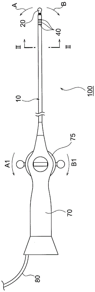
[0048] Figure 1 to Figure 4 The electrode probe shown is an ablation probe used in the treatment of cardiac arrhythmias.

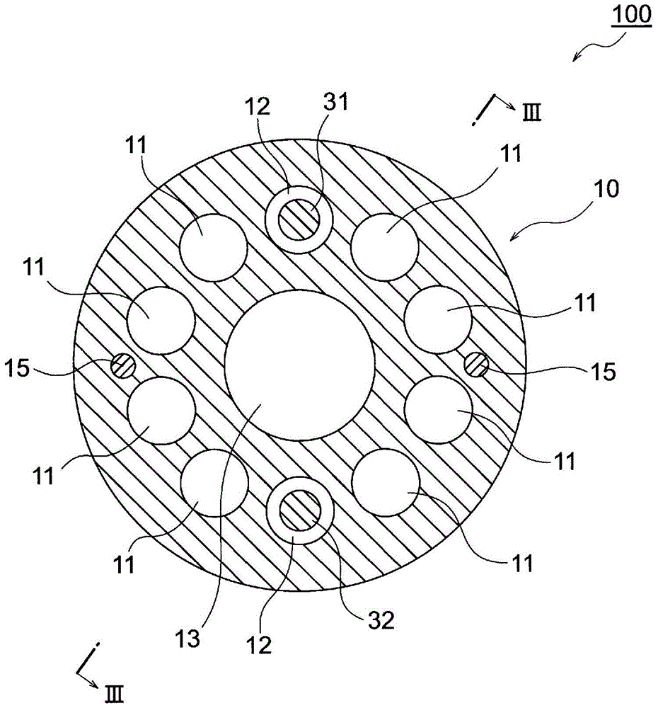
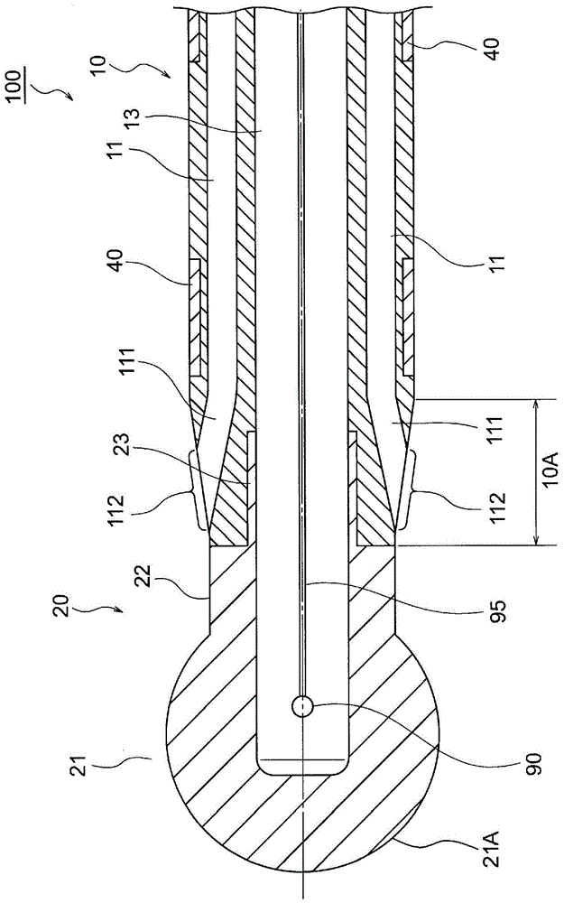
[0049] The ablation probe 100 of the present embodiment includes: a probe post 10 having a central lumen 13 through which a guide wire or the like passes, and 10 sub-lumens arranged around it at equiangular intervals (36° intervals) (as liquid 8 inner cavities 11 of the flow path, and 2 inner cavities 12 as the insertion passages of the pull wires 31, 32); the front end electrode 20, which is connected to the front end side of the probe column 10 and has a spherical part 21; the ring shape Electrode 40, it is installed on the front end portion of probe column 10; Control handle 70, it is connected with the rear end side of probe column 10; Liquid injection pipe 80; And temperature sensor (thermoelectric pair) 90, it is in...

no. 2 Embodiment approach >

[0118] Figure 5 The ablation probe 105 shown has a probe post 50 having 10 sub-lumens (eight lumens 51 serving as liquid flow channels, and two lumens serving as insertion passages for pulling wires). It has a tapered front-end diameter reduction portion 50A that is tapered toward the front-end direction, and eight flushing openings 512 for flushing liquid to the surface of the front-end electrode 20 are arranged on the front-end diameter reduction portion 50A, and the front end of the probe column 50 is narrowed. Eight inclined lumens 511 are formed inside the diameter portion 50A. The eight inclined lumens 511 communicate with each of the eight inner cavities 51 (non-inclined lumens) on the rear end side, and the sides face the radially outer side of the probe column 10. The inclined side extends toward the front end and reaches each of the flushing openings 512 .

[0119] In addition, in Figure 5 in, with Figure 4 Like components of the ablation probe 100 shown are gi...

Embodiment 1

[0133] for having image 3 as well as Figure 4 As shown in the cross-sectional configuration, the outer diameter of the probe post 10 (D 1 ) is 2.4mm, the above distance (L 1 ) is 2.63mm, the inclination angle (β) of the front-end reduced diameter portion 10A is 10.0°, the above-mentioned distance (L 2 ) is 1.21mm, the inclination angle (α) of the inclined lumen 111 is 5.0°, and the diameter (D 2 =D 1 +2(L 2 ·tanα-L 1 tanβ) is 1.68mm, (D 2 / D 1 ) of the ablation probe 100 with a value of 0.70 was compared with that of the ablation probe 100 using the analysis software "SoLiDWorks FLow SimuLATioN" (manufactured by DAssAuLTSysTEms SoLiDWorks CorPorATioN) in a state where the distal end part was immersed in blood and flushed with physiological saline. The presence of physiological saline in the liquid (blood and / or physiological saline) in contact with the distal end hemispherical surface 21A of the distal end electrode 20 is simulated.

[0134]As a result, the ratio of...


PUM


Abstract

An electrode catheter which has: a catheter shaft (10); and a tip electrode (20) having a spherical portion (21); and is provided with an irrigation mechanism; wherein a plurality of irrigation openings (112) are arranged at a tip reduced-diameter section (10A) of the shaft (10), a plurality of inclined lumens (111) are formed in the interior of the tip reduced-diameter section (10A), and the formula: D2 ≒ D1 +2 (L2·tanalpha-L1·tanbeta) applies, where (D1) is the outer diameter of the catheter shaft (10), (D2) is the diameter of the spherical portion (21), (L1) is the distance from the rear end of the tip reduced-diameter section (10A) to the tip edge of the irrigation openings (112), (L2) is the distance from the tip edge of the irrigation openings (112) to a maximum diameter section of the tip electrode (20), (beta) is the angle of incline of the tip reduced-diameter section (10A), and (alpha) is the angle of incline of the inclined lumens (111), the angle of incline (alpha) being 5.0-12.5° (excluding 9.1-9.3°). According to this electrode catheter, a liquid can be adequately contacted with a tip hemisphere of the tip electrode having the spherical portion.

Description

technical field [0001] The present invention relates to an electrode probe, and more specifically relates to an electrode probe having an electrode attached to the tip of the probe and a mechanism for flushing the electrode with liquid such as physiological saline. Background technique [0002] In an ablation catheter as an electrode probe, in order to cool the tip electrode which becomes high temperature during cauterization, and to stir / dilute the blood around the tip electrode so as to prevent thrombus from forming on the surface of the tip electrode, Use a structure with a flushing mechanism. [0003] As a conventional probe equipped with a flushing mechanism, a structure of the type in which physiological saline supplied to the inside of the tip electrode is sprayed from a plurality of openings formed on the surface of the tip electrode through the probe post (for example, refer to Patent Document 1 and Patent Document 2). [0004] Patent Document 1: Japanese Patent N...

Claims


Application Information

Patent Timeline
Patent Type & Authority Patents(China)
IPC IPC(8): A61B18/12
CPCA61B18/1492A61B2017/003A61B2017/00323A61B2018/00029A61B2018/00351A61B2018/00357A61B2018/00791A61B2018/1417A61B2218/002
Inventor 田中裕生子
Owner JAPAN LIFELINE CO LTD
Why Eureka
Try Eureka