Pilotless helicopter
An unmanned and helicopter technology, which is applied in the direction of rotorcraft, motor vehicles, aircraft control, etc., can solve the problem of aircraft out of control, achieve the effects of large payload, high work efficiency, and improved reliability and safety factor
- Summary
- Abstract
- Description
- Claims
- Application Information
AI Technical Summary
Problems solved by technology
Method used
Image
Examples
Embodiment 1
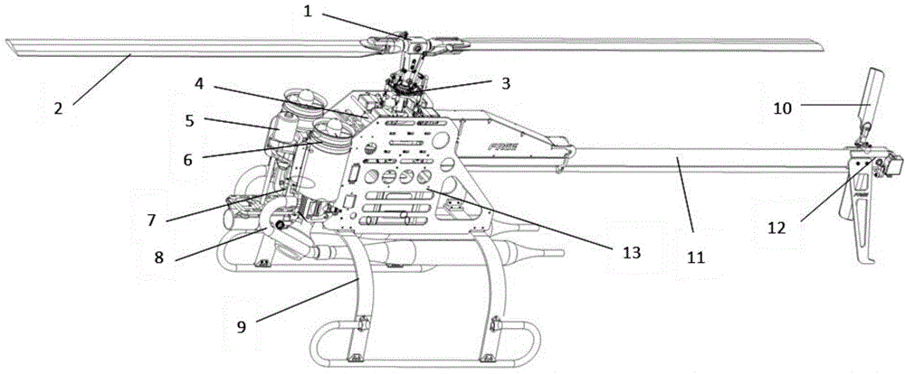
[0079] Such as figure 1 , shows a structural diagram of an unmanned helicopter that uses auxiliary lift-anti-torque-cooling function device to cool the engine and adopts 4-channel hybrid control swash plate, which is characterized in that it includes main rotor head 1, main rotor 2, swash plate Device 3, reduction box 4, starting device 5, at least one auxiliary lift-anti-torque-cooling function device 6, engine 7, exhaust pipe 8, landing gear 9, tail rotor 10, tail pipe 11, tail rotor device 12 and machine body frame13. The main rotor head 1 is installed above the reduction box 4; the main rotor 2 is installed at both ends of the main rotor head; the 4-channel swash plate control device 3 is installed below the main rotor head, fixed at The top of the box; the starting device 5 is installed on the front of the fuselage frame 13, above the engine 7; the engine 7 is installed on the front of the fuselage frame by suspension, and the landing gear 9 is installed on the machine ...
Embodiment 2
[0100] The structure of embodiment 2 is basically the same as that of embodiment 1, the difference is that there are two auxiliary lift-anti-torque-cooling functional devices, and the two ducts are symmetrically arranged on both sides of the central axis of the unmanned helicopter to ensure that there is no The stability of the roll control of the manned helicopter and the ease of arranging the center of gravity of the unmanned helicopter, the engine drives its rotation through the transmission parts, keeping the rotation direction of all the lift fans opposite to the rotation direction of the main rotor. The engine drives the lift fan to rotate through the transmission part. The transmission part can be any one of transmission belts, gears and shafts. The structure of the auxiliary lift-anti-torque-cooling function device is as follows: Figure 10 shown.
Embodiment 3
[0102] The structure of embodiment 3 is basically the same as that of the first two embodiments, the difference is that: the four steering gears of the 4-channel hybrid control swashplate are symmetrically distributed to a point on the main shaft axis of the main rotor;
[0103] Taking the forward direction of the unmanned helicopter as the central axis, the line connecting the installation positions of the first steering gear and the fourth steering gear forms an angle of 45 degrees with the central axis, and the connection line between the installation positions of the second steering gear and the third steering gear and the central axis At a 45-degree angle [the first and second steering gears are close to the nose; the third and fourth steering gears are close to the tail]; The connection line of the position and the central axis form an angle of 0 degrees, and the connection line of the installation position of the second servo and the third servo forms an angle of 90 degr...
PUM
 Abstract
Description
Claims
Application Information
 - R&D
- Intellectual Property
- Life Sciences
- Materials
- Tech Scout
- Unparalleled Data Quality
- Higher Quality Content
- 60% Fewer Hallucinations
Browse by: Latest US Patents, China's latest patents, Technical Efficacy Thesaurus, Application Domain, Technology Topic, Popular Technical Reports.
© 2025 PatSnap. All rights reserved.Legal|Privacy policy|Modern Slavery Act Transparency Statement|Sitemap|About US| Contact US: help@patsnap.com


