Road finishing machine with pushing device

A technology of a pushing device and finishing machine, which is applied in road repairing, accessories for easy driving, roads, etc., and can solve the problems that road finishing machines require a large space, high manufacturing cost, and difficult to refit.

Active Publication Date: 2015-02-25
JOSEPH VOEGELE AG
View PDF7 Cites 3 Cited by
  • Summary
  • Abstract
  • Description
  • Claims
  • Application Information

AI Technical Summary

Problems solved by technology

The disadvantage is that the hydraulic circuit has a complex design and requires a lot of space on the road finishing machine
In addition, components used in hydraulic circuits, such as hydraulic pumps or control valves, must be serviced regularly
Such propulsion devices are expensive to manufacture and difficult to retrofit to existing road finishing machines

Method used


Image

  • Road finishing machine with pushing device
  • Road finishing machine with pushing device
  • Road finishing machine with pushing device

Examples


Embodiment Construction

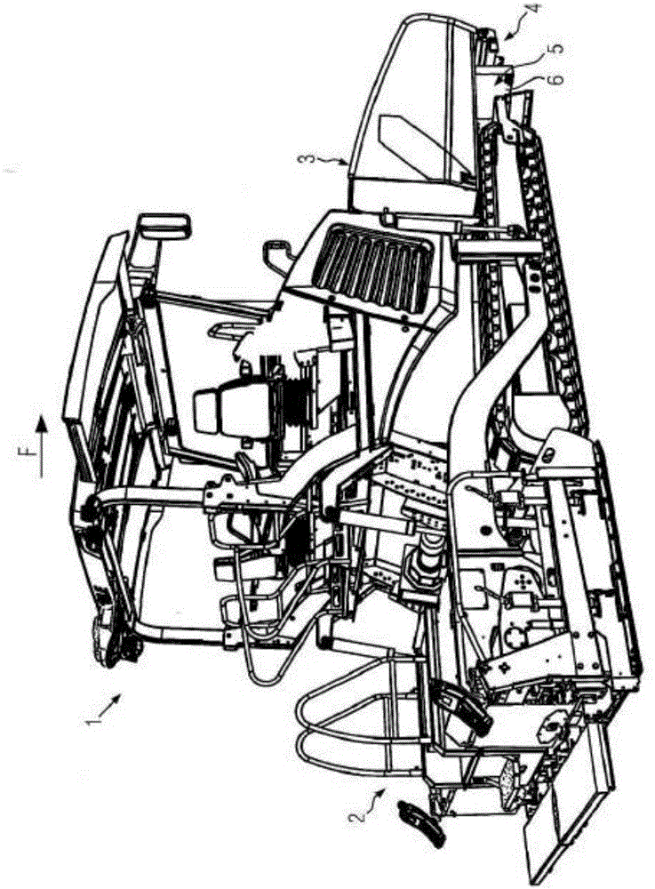
[0041] figure 1 A road finishing machine 1 is shown with a screed 2 and a material hopper 3 arranged in front (seen in the paving direction F) for receiving the paving material. The pushing device 4 according to the present invention is arranged in front of the material hopper 3 . The pushing device 4 is installed at the chassis 5 of the road finishing machine 1 . Specifically, the pushing device 4 is fixed to the cross member 6 of the chassis 5 .

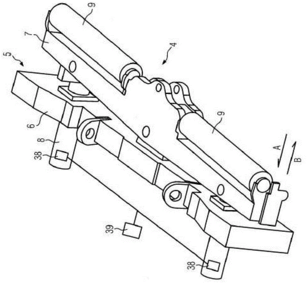
[0042] figure 2 The pushing device 4 is shown detached from the road finishing machine 1 in an enlarged perspective representation. The pusher 4 has a docking assembly 7 and first and second absorber units 8 . Two absorber units 8 are fastened to the cross member 6 of the chassis 5 . The docking assembly 7 is mounted so as to be movable relative to said cross member 6 of the chassis 5 . The docking assembly 7 is movable towards and away from the cross member 6 . If the load L acts on the butt assembly 7 from the front on o...


PUM


Abstract

The disclosure relates to a road finishing machine with a chassis and a pushing device. The pushing device comprises at least one docking assembly and at least one absorber unit. The absorber unit is fixed to the chassis of the road finishing machine and comprises at least one piston-cylinder unit which comprises a cylinder and a working piston movable therein which subdivides the piston-cylinder unit into at least one first and one second chambers and is coupled to the docking assembly. The docking assembly may be positioned, by the movably mounted working piston, relative to the chassis between an extended position and at least one retracted position. In the piston-cylinder unit, at least one flow channel is provided between the first and the second chambers for letting a fluid enclosed in the piston-cylinder unit pass through, the fluid being prestressed in the extended position.

Description

technical field [0001] The present invention relates to a road finishing machine according to the preamble of claim 1 . Background technique [0002] Such road finishing machines are used in practice for docking to wagons for material transfer. During this process, it is important that there is no jerk from the material, which can cause damage to the pavement, as transferred from the material supply vehicle to the road finishing machine. In practice, therefore, road finishing machines are used which, in the front (seen in the paving direction), comprise at their chassis a pushing device, by means of which the road finishing machine can buffer the docking of the material supply vehicle. [0003] EP 2527534 A1 of the applicant discloses a road finishing machine with a pushing device movably mounted at the chassis, which preferably comprises at least one friction spring as absorption member. With the latter, the damping of the wagon to which it is docked is good, but as a res...

Claims


Application Information

Patent Timeline
Patent Type & Authority Applications(China)
IPC IPC(8): E01C23/06
CPCB60D3/00E01C19/48E01C2301/08E01C23/06
Inventor T·高特巴姆T·施密特
Owner JOSEPH VOEGELE AG
Why Eureka
Try Eureka