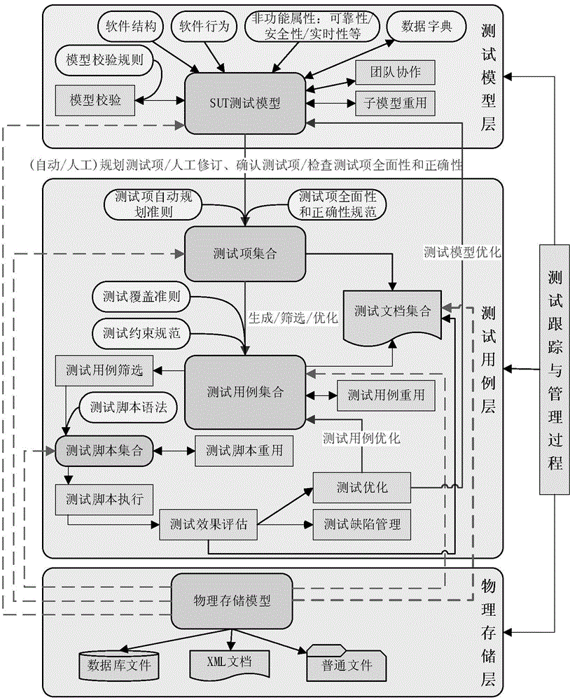
Embedded software black-box test case generation method based on static models
An embedded software and black-box testing technology, applied in software testing/debugging, etc., can solve problems such as inability to guarantee the quality of test cases, low test efficiency, and test lag, so as to ensure reproducibility and comprehensibility, and improve test efficiency , to ensure the effect of effectiveness
- Summary
- Abstract
- Description
- Claims
- Application Information
AI Technical Summary
Problems solved by technology
Method used
Image
Examples
specific Embodiment approach 1
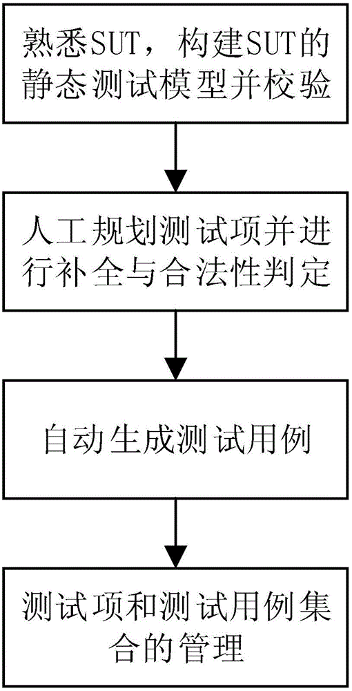
[0035] Specific implementation mode one: combine figure 2 , image 3 Describe this implementation mode, this implementation mode comprises the following steps:
[0036] Step 1. After getting familiar with the software under test, use the structural analysis method to construct the static model of the embedded software by using data flow graph, fault tree, causal graph, decision table, nesting mechanism between graphs and extended semantics of graphs to describe Static testing requirements for embedded software;
[0037] Step 2. Verify the static model of the embedded software built in step 1, and manually plan the test items according to the test purpose, then automatically complete the test items and determine their legality, and finally fill in the name of the test item;
[0038] The completion of the test items is aimed at achieving "internal connectivity of the test items", and is realized by using the classic traversal algorithm of the graph, finally generating complet...
specific Embodiment approach 2
[0053] Specific implementation mode two: combination figure 2 , image 3 Describe this implementation mode, the difference between this implementation mode and specific implementation mode 1 is:
[0054] The structured method described in step 1 is a common method for requirements analysis and design of embedded software. The data flow diagram is the product of the requirements analysis and overall design stage of embedded software. The fault tree, cause-and-effect diagram and decision table are the traditional black-box test common means of design.
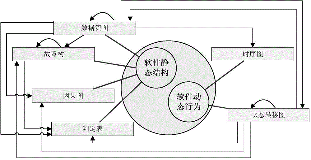
[0055] The nesting mechanism between graphics is as image 3 As shown, the connecting lines with arrows represent the nesting relationship between graphs (the starting point is the parent graph, and the end point is the sub graph), including:
[0056] (1) The data flow graph is constructed hierarchically, specifically the data processing nested sub-data flow graph of the data flow graph;
[0057] (2) Data processing nested f...
specific Embodiment approach 3
[0059] Specific implementation mode three: combination figure 2 , image 3 Describe this implementation mode. The difference between this implementation mode and the specific implementation mode 1 or 2 is that the extended semantics of the graphics described in step 1 include:
[0060] (1) Added test semantics to the primitives of the data flow graph, including added backcalculation program, time domain, hardware and interrupt attributes for data processing;
[0061] (2) Added test semantics to the primitives of the fault tree, including the CMP attribute added to the bottom event (this attribute quantitatively describes the occurrence of the bottom event);
[0062] (3) Added test semantics to the decision table, including automatically generating a decision table according to logical expressions, and adding preconditions for the decision table.
PUM
 Abstract
Description
Claims
Application Information
 - R&D
- Intellectual Property
- Life Sciences
- Materials
- Tech Scout
- Unparalleled Data Quality
- Higher Quality Content
- 60% Fewer Hallucinations
Browse by: Latest US Patents, China's latest patents, Technical Efficacy Thesaurus, Application Domain, Technology Topic, Popular Technical Reports.
© 2025 PatSnap. All rights reserved.Legal|Privacy policy|Modern Slavery Act Transparency Statement|Sitemap|About US| Contact US: help@patsnap.com


