

Durable rainproof and windproof distribution box
A distribution box, durable technology, applied in the substation/distribution device shell, etc., can solve the problems of heat dissipation, rainproof, and windproof in the distribution box, achieve good heat dissipation, breathable and dry performance, low failure rate, The effect of improving sensitivity
- Summary
- Abstract
- Description
- Claims
- Application Information
AI Technical Summary
Problems solved by technology
Method used
Image

Examples
Embodiment Construction
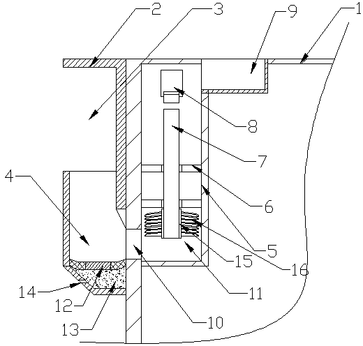
[0029] The present invention is described in further detail now in conjunction with accompanying drawing. These drawings are all simplified schematic diagrams, which only illustrate the basic structure of the present invention in a schematic manner, so they only show the configurations related to the present invention.
[0030] Such as figure 1 As shown, a durable rainproof and windproof distribution box of the present invention includes a distribution box closing mechanism, a rainproof and windproof mechanism and a distribution box body,
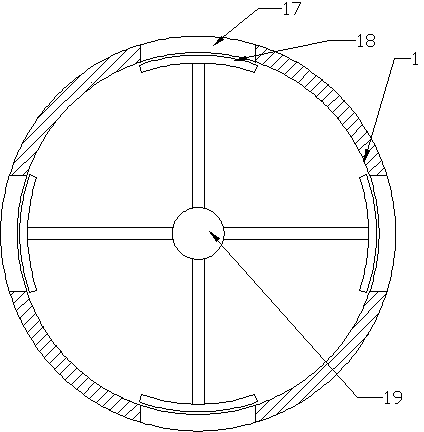
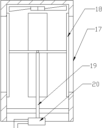
[0031] The closed structure of the distribution box includes a ventilation assembly arranged on the wall of the distribution box. The body of the distribution box is cylindrical. The axis of the opening 17 is parallel to the axis of the distribution box body. The ventilation part includes a number of shielding plates corresponding to the number of vents 17 and a shielding plate driving mechanism. The shielding plate is arc-shaped, and the ...
PUM
| Property | Measurement | Unit |
|---|---|---|
| Angle | aaaaa | aaaaa |
Abstract
Description
Claims
Application Information