RF impedance matching debugging method

A technology of impedance matching and debugging method, applied in impedance matching network, multi-terminal pair network, etc., can solve the problems of complicated use and impossible pre-installation of circuit simulation software, so as to improve the calculation speed and overcome the computer simulation method and manual calculation method. Effect

Inactive Publication Date: 2015-02-25
重庆蓝岸科技股份有限公司
View PDF3 Cites 12 Cited by
  • Summary
  • Abstract
  • Description
  • Claims
  • Application Information

AI Technical Summary

Problems solved by technology

Because software such as computer simulation is designed for different functions and not just for impedance matching, it is more complicated to use. The designer must be familiar with inputting a large number of data in the correct format, and the designer also needs to have the ability to learn from a large number of output results. the skill of finding useful data, plus it is unlikely that circuit simulation software will come pre-installed on a computer unless the computer is made specifically for this purpose

Method used


Image

  • RF impedance matching debugging method
  • RF impedance matching debugging method
  • RF impedance matching debugging method

Examples


Embodiment

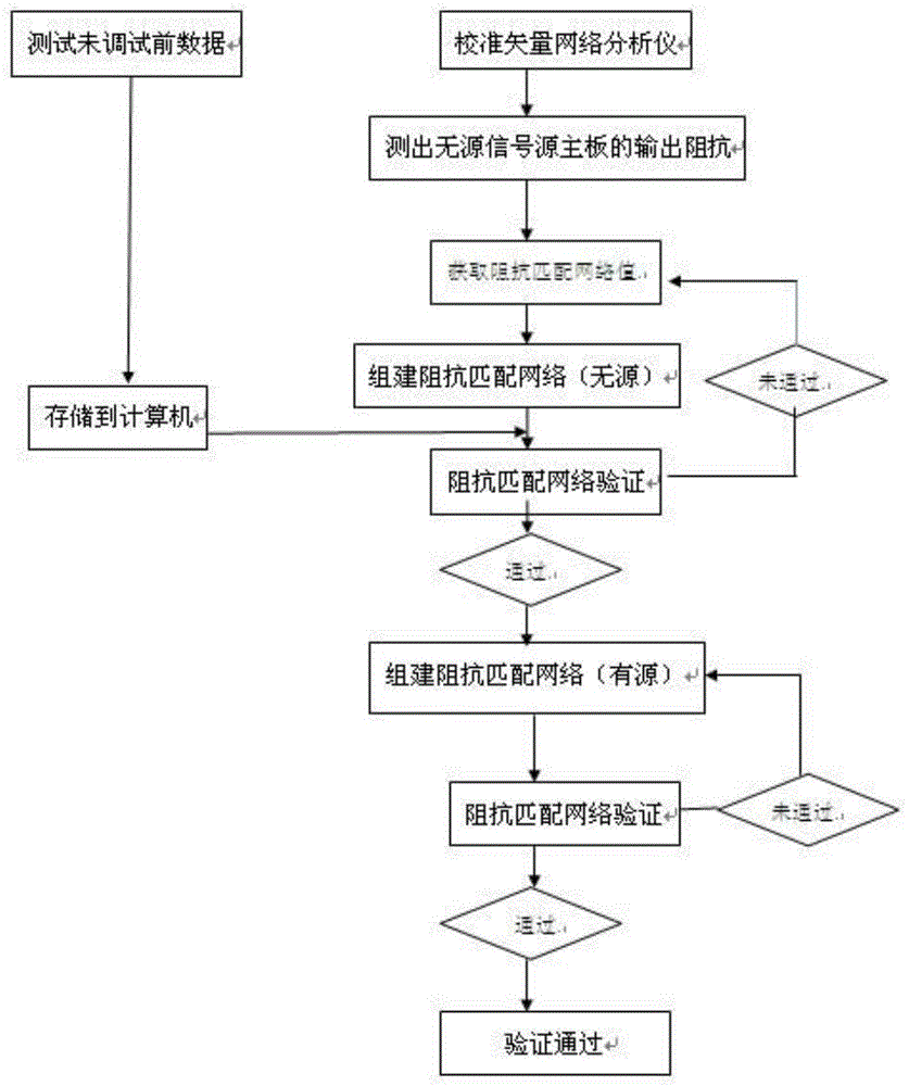
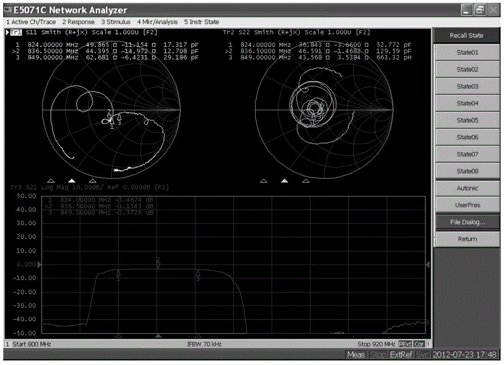
[0052] Take debugging the GSM850 circuit board of PA as an example, figure 2 It is the Smith circle diagram of the present embodiment; image 3 The vector network analyzer of the present embodiment measures the RF parameter diagram; Figure 4 It is the Load Pull diagram of the embodiment of the present invention. Designed at 824-849MHz PA operating frequency, signal source impedance: Z S =(35.1-J47.5)Ω, namely figure 2 1 o'clock position. Debugging according to the steps of the present invention, the result is that after the parallel inductance is 8.2nH, the signal source impedance is Z S =(50.5+J49.7)Ω, that is: figure 2in the 2 o'clock position. At the same time, after the series capacitor is 3.9pF, the signal impedance is Z L =(50.5+j0.2)Ω, that is: figure 2 in the 3 o'clock position. To make it meet the index requirement that the voltage standing wave ratio is less than 3.5 in the frequency range of 400-1200, by comparison Figure 4 , so as to optimize the PA...


PUM


Abstract

The invention discloses an RF impedance matching debugging method. The method mainly comprises the steps that data, before optimization, of a signal source are tested; a vector network analyzer performs calibration; the vector network analyzer acquires output impedance of a main board of the signal source through measurement; an impedance matching network value is acquired by using Smith-Chart software in cooperation with load pull data; an impedance matching network is established; the impedance matching network is verified. During RF impedance matching debugging, the impedance matching network value is acquired by using the Smith-Chart software in cooperation with the load pull data; in the debugging process, a computer is used for calculation in cooperation with the Smith-Chart software and the load pull data; in this way, accuracy is guaranteed on the premise that visibility and clearness of physical concepts are guaranteed; meanwhile, the calculation speed is greatly increased, and the defects of a computer simulation method and the defects of a manual calculation method are overcome.

Description

technical field [0001] The invention relates to an impedance matching debugging method, in particular to a radio frequency impedance matching debugging method. Background technique [0002] Impedance matching refers to a working state in which the load impedance and the internal impedance of the signal source are adapted to each other to obtain the maximum power output. There are many methods for impedance matching debugging, but each has its own disadvantages. For example: computer simulation method and manual calculation method. Because software such as computer simulation is designed for different functions and not just for impedance matching, it is more complicated to use. The designer must be familiar with inputting a large number of data in the correct format, and the designer also needs to have the ability to learn from a large number of output results. The skill to find useful data, plus it's unlikely that circuit simulation software will come preloaded on a comput...

Claims


Application Information

Patent Timeline
Patent Type & Authority Applications(China)
IPC IPC(8): H03H11/30
Inventor 张雷
Owner 重庆蓝岸科技股份有限公司
Why Eureka
Try Eureka