Low-resistance efficient column tray

A low-resistance and high-efficiency technology, applied in the fields of dust washing equipment, gas-liquid heat transfer, and mass transfer, it can solve the problems of large resistance and large gas energy loss, and achieve the effect of large operation elasticity, low gas flow resistance and no amplification effect.

Active Publication Date: 2015-03-04
TIANJIN AOZHAN XINGDA TECH
View PDF6 Cites 7 Cited by
  • Summary
  • Abstract
  • Description
  • Claims
  • Application Information

AI Technical Summary

Problems solved by technology

The disadvantages of this structure are: firstly, the gas-liquid flow mode is still a cross-flow mode, and the improvement of the plate efficiency is restricted; secondly, the gas-liquid kinetic energy is transferred in parallel flow process, the energy loss of the gas is large, and the resistance of each tray is relatively large , generally at 400-600Pa, such trays include New-Vst new vertical sieve trays, CTST three-dimensional mass transfer trays, CJST radial side jet trays, JCPT trays, etc.

Method used


Image

  • Low-resistance efficient column tray
  • Low-resistance efficient column tray
  • Low-resistance efficient column tray

Examples


Embodiment 1

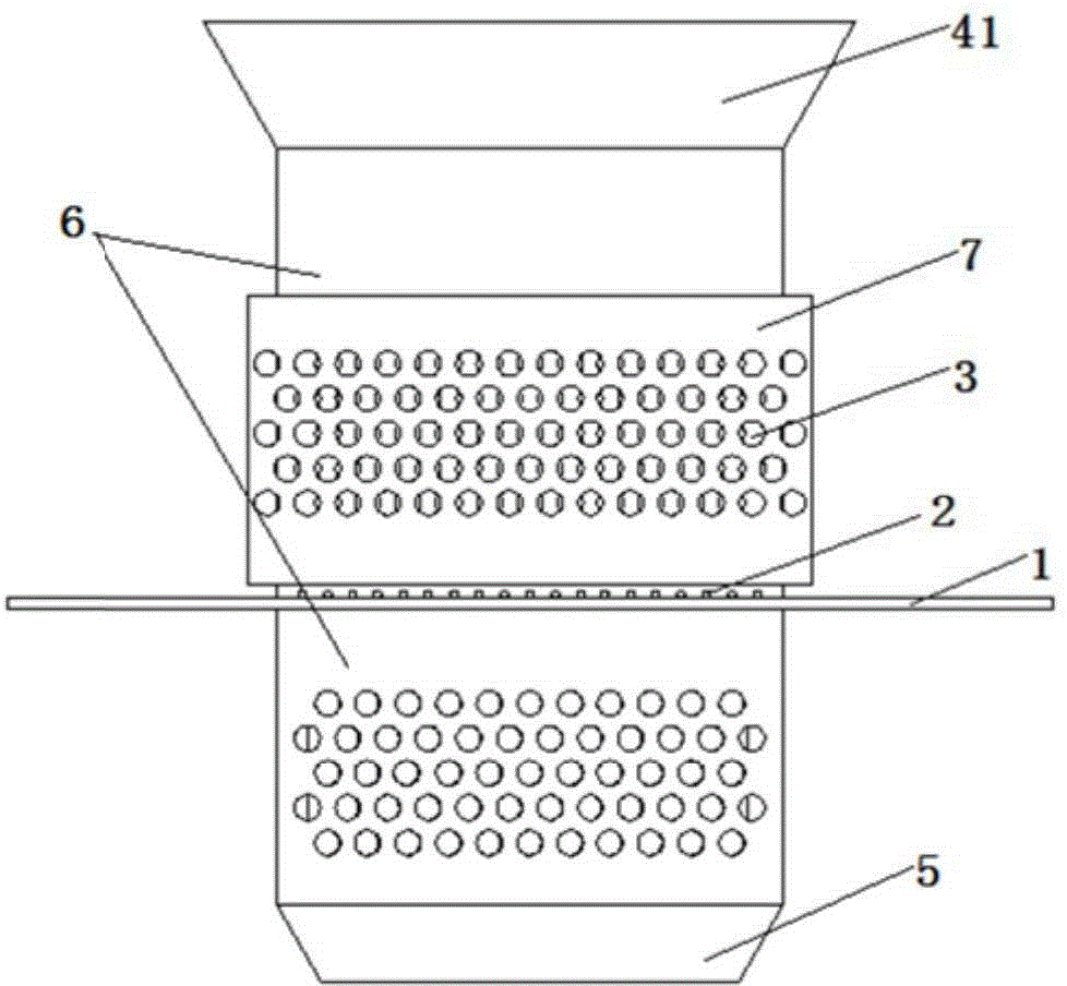
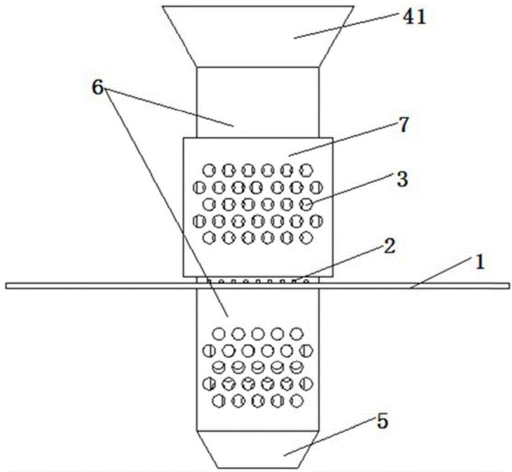
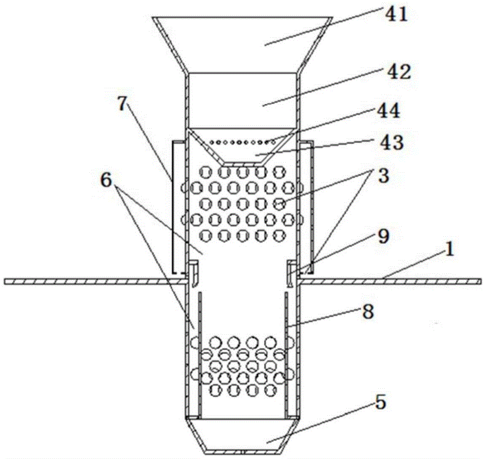
[0043] Such as Figure 1-7 A low-resistance high-efficiency tray is shown, including a tray 1 and a number of caps 6 that pass through the tray 1 and are welded to the tray 1 (and the caps 6 protrude upward or downward from the plane of the tray 1 by 100mm-250mm , the specific height is designed according to the actual height of the tower body), the top of the cap 6 is provided with a sump 4, the bottom is provided with a downcomer structure 5, the part of the cap positioned at the upper end of the tray 1 and the part of the cap positioned at the lower end of the tray 1 There are several rows of sieve holes 3 staggered in the middle of the tray, and an outer liquid-retaining sieve plate 7 concentric with it is arranged on the periphery of the upper cap at the upper end of the tray, and the outer liquid-retaining sieve plate 7 is welded to the side wall of the cap. cavity structure, and the bottom of the cavity structure is provided with a number of sieve holes 3, which are use...

Embodiment 2

[0049] Such as Figure 9 and 10 As shown, the present invention provides a low-resistance high-efficiency tray, comprising a tray 1 and a cap 6 (the cap 6 is a cylindrical structure with openings at both ends), the top of the cap 6 is provided with a sump 4, and the bottom A downcomer structure 5 is provided, and several rows of sieve holes 3 are distributed in parallel in the middle part of the part of the cap located at the upper end of the tray 1 and the part of the cap located at the lower end of the tray 1. The outer liquid-retaining sieve 7 concentric with it (and the outer liquid-retaining sieve protrudes about 5-150 mm from the side wall of the cap), and the outer liquid-retaining sieve 7 and the side wall of the cap are welded into a cavity structure , the bottom of the cavity structure is provided with several sieve holes 3, and the side wall of the outer liquid retaining sieve plate 7 is also provided with several rows of sieve holes 3 in parallel; On the side wal...

Embodiment 3

[0055] Such as Figure 11 As shown, the present invention provides a low-resistance high-efficiency tray, comprising a tray 1 and a cap 6 (the cap 6 is a cylindrical structure with openings at both ends), the top of the cap 6 is provided with a sump 4, and the bottom A downcomer structure 5 is provided, and several rows of sieve holes 3 are distributed in parallel in the middle part of the part of the cap located at the upper end of the tray 1 and the part of the cap located at the lower end of the tray 1. The outer liquid-retaining sieve 7 concentric with it (and the outer liquid-retaining sieve protrudes about 5-150 mm from the side wall of the cap), and the outer liquid-retaining sieve 7 and the side wall of the cap are welded into a cavity structure , the bottom of the cavity structure is provided with several sieve holes 3, and the side wall of the outer liquid retaining sieve plate 7 is also provided with several rows of sieve holes 3 in parallel; There is a row of liqu...


PUM


Abstract

The invention provides a low-resistance efficient column tray. Cover hoods are welded on column plates; outer layer liquid blocking sieve plates with sieve holes are arranged at the peripheries of the outer parts of the side walls of the cover hoods above the column plates for secondary gas-liquid dispersion mass transfer; a row of small liquid distribution holes are formed in the side surfaces of the cover hoods, close to the column plates; a liquid collecting groove is formed above the cover hoods; the cover hoods protrude out of the plane of the column plates by a certain height so as to prevent solid substances from blocking the cover hoods and the sieve holes; an oblique plate is arranged at the part corresponding to the small liquid distribution holes in each cover hood; a narrow gap is formed between the oblique plate and the side walls of the cover hoods for distributing a liquid; a plurality of sieve holes are also formed in the side walls of the cover hoods at the lower parts of the column plates; meanwhile, an inner layer liquid blocking sieve plate is arranged in the side wall of the cover hood below the column plates for secondary gas-liquid dispersion mass transfer; a plurality of liquid exhaust holes are formed in the bottom of the cover hoods for liquid distribution and dropping, and meanwhile play a role of liquid sealing. The low-resistance efficient column tray has the advantages that the gas flow resistance is low; the gas-liquid contact effect is good; the antiblocking effect is good; the column plate efficiency is high; the manufacture and running costs are low; the column tray is convenient to overhaul.

Description

technical field [0001] The invention relates to gas-liquid heat transfer, mass transfer and dust washing equipment in chemical engineering, specifically a low-resistance high-efficiency tray for chemical mass transfer, washing and separation. Background technique [0002] Gas-liquid mass transfer internals are divided into two categories: plate tower and packed tower. The resistance of plate tower is generally 8-10 times that of packed tower. Therefore, in the field where the resistance drop requirement of the whole tower is small, only packed tower can be used. Trim. The advantage of packed tower internals is that the gas flow resistance is small and the mass transfer efficiency is high. The disadvantage is that when the liquid flow rate is small, it is difficult to evenly distribute the liquid. It is often due to insufficient wetting of the packing and the gas-liquid cannot be forced to contact the mass transfer. For washing and dust removal The efficiency of the working ...

Claims


Application Information

Patent Timeline
Patent Type & Authority Applications(China)
IPC IPC(8): B01D3/22B01D53/18
Inventor 张兵李建明阮杰
Owner TIANJIN AOZHAN XINGDA TECH
Why Eureka
Try Eureka