Molding and manufacturing process for hinge

A manufacturing process and hinge technology, which is applied in the direction of folding panels, building structures, door/window accessories, etc., can solve the problems of failing to meet the low-cost production needs of enterprises, failing to meet the strength requirements of hinges, and generating too much cutting waste and other issues, to achieve the effect of improving production efficiency and production efficiency, simplifying the production and processing process, and improving utilization rate

Active Publication Date: 2015-03-04
WENZHOU YANG THAI FASTENERS
View PDF6 Cites 5 Cited by
  • Summary
  • Abstract
  • Description
  • Claims
  • Application Information

AI Technical Summary

Problems solved by technology

[0004] Although the beneficial effect of the manufacturing method of high-strength aluminum alloy hinges is that it is convenient to process products with high strength, good surface treatment and corrosion resistance, and meets precision requirements, the manufacturing method of this high-strength aluminum alloy hinge is Extrusion, stamping and other composite processing methods are used to realize the production and manufacture of hinges. For the hinges involved in the present invention, if high-strength aluminum alloy hinges are used for production, excessive cutting waste will occur. , reduce the utilization rate of raw materials, the production steps are too complicated, and the production efficiency is reduced. At the same time, the raw materials are cut off many times, so that the produced hinges cannot meet the strength requirements, and the mechanical properties are poor, which cannot meet the pursuit of low cost, high efficiency and large quantities of enterprises. manufacturing production needs

Method used


Image

  • Molding and manufacturing process for hinge
  • Molding and manufacturing process for hinge
  • Molding and manufacturing process for hinge

Examples


Embodiment Construction

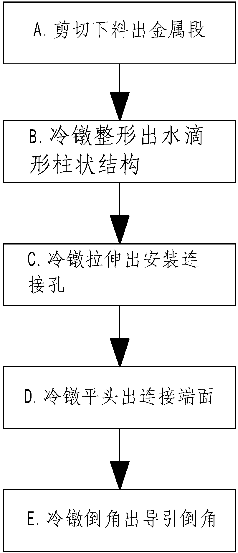
[0034] refer to figure 1 An embodiment of a hinge forming manufacturing process of the present invention will be further described.

[0035] A hinge forming manufacturing process is characterized in that it comprises the following steps:

[0036] A. Cutting and blanking: use metal bars with standard diameters as raw materials and use shears to cut metal bars into metal segments with fixed length specifications;

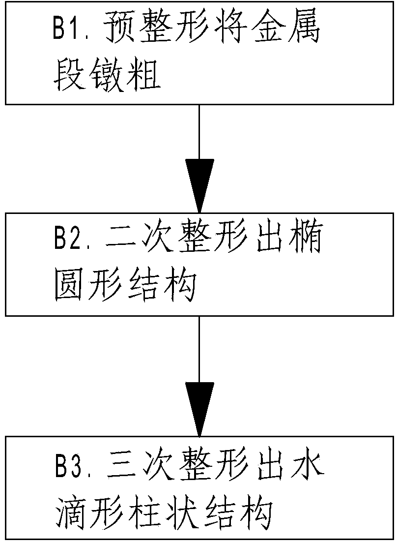
[0037] B. Cold heading shaping: use a cold heading machine with multiple molds to cold-head the metal segment in step A step by step to form a drop-shaped columnar structure;

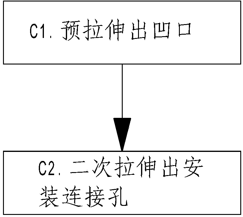
[0038] C. Cold heading and stretching: use a cold heading machine to cooperate with multiple molds to cold-head the metal section processed in step B to form the installation connection hole;

[0039] D. Cold heading flat head: use a cold heading machine to cooperate with the mold to cold-head the two ends of the metal section processed in step C to form the connection end surface;

[0040] ...


PUM

PropertyMeasurementUnit
surface roughnessaaaaaaaaaa
surface smoothnessaaaaaaaaaa

Abstract

The invention discloses a molding and manufacturing process for a hinge, and aims at providing a molding and manufacturing process, wherein the molding and manufacturing process meets the demands of production and manufacture of a drop-shape cylindrical hinge, improves the utilization rate of raw materials, guarantees the mechanical performances of the produced hinge, and meets the requirements for high strength. The main points of the technical scheme are that the process comprises the following steps: A, cutting fed materials, i.e., employing a cutter to cut a metal rod serving as a raw material into metal segments with a specific standard; B, cold-heading shaping, i.e., employing a cold-heading machine for enabling the metal segments formed at the step Ato form drop-shape cylindrical structures in a cold-heading manner; C, cold-heading stretching, i.e., enabling the metal segments formed at the step B to form installation connecting holes in a cold-heading manner; D, cold-heading leveling, i.e., enabling the metal segments formed at the step C to form connecting end faces in a cold-heading manner; E, cold-heading chamfering, i.e., enabling the metal segments formed at the step D to form guide chamfers in a cold-heading manner. The process employs a method of cold heading to form the drop-shape cylindrical hinge, improves the production efficiency of an enterprise, and reduces the production cost.

Description

technical field [0001] The invention relates to the technical field of mechanical processing, and more specifically, it relates to a forming and manufacturing process of a hinge. Background technique [0002] Hinge is also known as hinge, and its official name is hinge. The common connection form is a two-fold combination, which is a part that connects two parts of an object and enables them to move. It is generally used to connect the door frame and the door leaf, so that the door frame or door leaf can be opened smoothly. The function of closing, in order to let people get better enjoyment, a hydraulic hinge, also known as a damping hinge, is characterized by a buffer function when the cabinet door is closed, which minimizes the contact with the cabinet body when the cabinet door is closed. Noise from collisions. In the prior art, the hinges are generally made of steel or copper, which are produced by cutting, stamping and other composite processing methods. Therefore, the...

Claims


Application Information

Patent Timeline
Patent Type & Authority Applications(China)
IPC IPC(8): B21K13/02
Inventor 周建
Owner WENZHOU YANG THAI FASTENERS
Why Eureka
Try Eureka