Nanoscale component laser sintering molding method and device

A technology of laser sintering molding and parts, which is applied in the direction of improving process efficiency and energy efficiency, and can solve the problems that the molding accuracy cannot meet precision components, etc., and achieve good market application prospects, positive technical effects, and droplet cladding position controllable effect

Active Publication Date: 2015-03-04
SOUTH CHINA UNIV OF TECH
View PDF6 Cites 3 Cited by
  • Summary
  • Abstract
  • Description
  • Claims
  • Application Information

AI Technical Summary

Problems solved by technology

However, with the development of micro-nano precision manufacturing, the molding accuracy of existing laser sintering molding equipment still cannot meet the requirements of precision components, such as precision biological brackets, aerospace precision instruments and optoelectronic components, etc.

Method used


Image

  • Nanoscale component laser sintering molding method and device
  • Nanoscale component laser sintering molding method and device

Examples


Embodiment

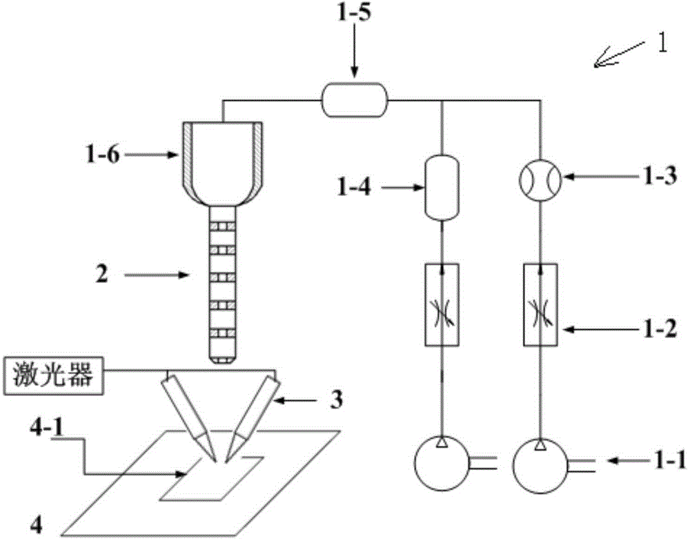
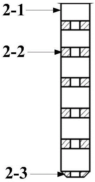
[0040] Such as figure 1 , 2 shown. The present invention is a kind of laser sintering forming device of nanoscale components, comprising mixed sample feeding system 1, aerodynamic lens 2, confocal laser group 3 and workbench 4; workbench 4 adopts high precision workbench, which has the same The movement accuracy of the parts forming accuracy is the same order of magnitude.

[0041] The mixed sampling system 1 is connected to an aerodynamic lens 2, and the aerodynamic lens 2 is located above the workbench 4;

[0042] The mixed sampling system 1 includes a buffer cavity 1-6, the inner wall of the buffer cavity 1-6 shrinks gradually from top to bottom, or the arc between the inner wall and the inner bottom wall of the buffer cavity 1-6 transition;

[0043] The confocal laser group 3 is located between the aerodynamic lens 2 and the table 4 .

[0044] The mixed sampling system 1 also includes a sequentially connected sampling mechanism and a mixing chamber 1-5 for forming an ...


PUM

PropertyMeasurementUnit
Reynolds numberaaaaaaaaaa

Abstract

The invention discloses a nanoscale component laser sintering molding method and device. The nanoscale component laser sintering molding device comprises a mixed sample feeding system, an aerodynamic lens, a confocal laser group and a worktable; the mixed sample feeding system is provided with a buffer cavity. The nanoscale component laser sintering molding method comprises the steps of placing nanoparticle powder into a powder storage cavity, carrying the powder into a mixing cavity through air, adequately mixing the powder and another branch circuit of air, facilitating the obtained aerosol flow to enter the buffer cavity, further mixing the gas and nanoparticle powder, and lowering the pressure and flow rate to obtain a fluid with a Reynolds number of 200 to 700; facilitating the fluid to enter a cylindrical cavity in a laminar flow form, and spraying out the fluid in a single-particle flow form after the fluid passes through gathering holes in each lens and is focused; receiving the particles by a sintering substrate which is coated with vacuum grease on the worktable, and melting the particles by the confocal laser group; acquiring a two-dimensional pattern with nanoscale molding precision by virtue of the movement of the worktable in an X direction and a Y direction; gradually laminating the particles to obtain a component with the nanoscale molding precision by virtue of the movement of the worktable in a Z-axis direction.

Description

technical field [0001] The invention relates to laser sintering molding equipment, in particular to a method and device for laser sintering molding of nanoscale components. Background technique [0002] 3D printing technology is a very popular manufacturing technology with a wide range of industrial application prospects. Different from traditional excision processing technology, 3D printing is a technology that uses adhesive materials such as molten metal, powder or polymer, and uses the principle of layer-by-layer stacking to construct models. [0003] Commonly used 3D printing methods use adhesives to bond powder layers to form thin layers; spray molten plastic from the nozzle, and then bond to form thin layers after the plastic solidifies; or use photosensitive materials to be stacked layer by layer through light curing and other methods. With 3D printing, models of almost any shape can in principle be produced. [0004] However, machining accuracy is the bottleneck th...

Claims


Application Information

Patent Timeline
Patent Type & Authority Applications(China)
IPC IPC(8): B29C67/00B22F3/105
CPCY02P10/25
Inventor 汤勇张仕伟曾健李文博陈灿
Owner SOUTH CHINA UNIV OF TECH
Why Eureka
Try Eureka