
Triple-speed conveying line

A conveying line, double-speed technology, applied in the field of triple-speed conveying line, can solve the problems that the maximum conveying speed is difficult to meet the production requirements, is not controlled, and the weight is limited, and achieves the effect of increasing the bearing weight, prolonging the service life, and not easy to wear

Inactive Publication Date: 2015-03-04
SUZHOU HUQIANG ELECTRIC EQUIP
View PDF7 Cites 2 Cited by
  • Summary
  • Abstract
  • Description
  • Claims
  • Application Information

AI Technical Summary

Problems solved by technology

[0003] Its shortcoming is that: the ordinary outer chain plate 3 that makes up the ordinary chain has to bear the pressure of the load and the sliding friction between the transmission track while bearing the pulling force. The ordinary outer chain plate 3 and the track where it is worn; the lack of structure limits the weight carried; the conveying speed is completely determined by the motor speed and the nominal diameter of the ordinary single-row gear 5 that drives the ordinary chain. The maximum conveying speed It is difficult to meet the contemporary high-efficiency production requirements; the movement or stop of the tooling plate at different stations is not controlled

Method used


Image

  • Triple-speed conveying line
  • Triple-speed conveying line
  • Triple-speed conveying line

Examples


Embodiment Construction

[0017] The preferred embodiments of the present invention will be described in detail below in conjunction with the accompanying drawings, so that the advantages and features of the present invention can be more easily understood by those skilled in the art, so as to define the protection scope of the present invention more clearly.

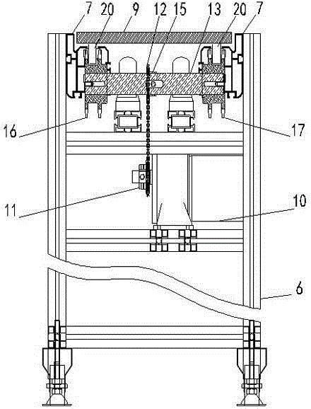
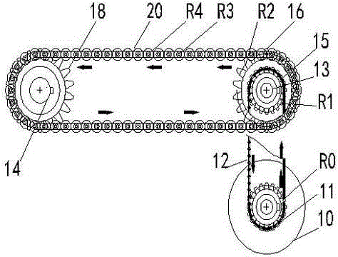
[0018] as attached Figure 2~5 Shown is a kind of triple speed chain conveyor line of the present invention, comprising: frame 6, motor gear 11, triple speed chain 20, blocking device 8, tooling plate 9; Described frame 6 is provided with motor 10 and Two mutually parallel tracks 7, described track 7 is parallel with frame 6; One end of described track 7 is provided with transmission shaft one 13, and the other end is provided with transmission shaft two 14, and described transmission shaft one 13 and transmission shaft two 14 are mutually parallel; Described transmission shaft one 13, transmission shaft two 14 are perpendicular to track; The mid...


PUM


Abstract

The invention discloses a triple-speed conveying line. The triple-speed conveying line comprises a machine frame, wherein a motor, a track and a retaining device are arranged on the machine frame; a transmission shaft I and a transmission shaft II which are parallel to each other are vertically arranged on the track; a gear I, a gear II and a gear III are arranged on the transmission shaft I; a gear IV and a gear V are arranged on the transmission shaft II; the gear II and the gear IV are connected through a triple-speed chain, and the gear III and the gear V are connected through a triple-speed chain; the motor drives a motor gear on an output shaft of the motor and drives the gear I through an ordinary chain on the motor gear, the gear I drives the gear II and the gear III through the transmission shafts, and the gear II and the gear III drive tool device plates on the gear II and the gear III through the triple-speed chains and convey objects at a speed which is triple the linear velocity of the motor; when the tool device plates are required to stop, the retaining device is operated and controlled to retain the tool device plates, and an operating and controlling device is removed when the tool device plates are required to continue to move. The triple-speed conveying line disclosed by the invention has the advantages of high conveying speed, wear resistance, high load carrying capacity and high efficiency.

Description

technical field [0001] The invention relates to a triple-speed conveying line. Background technique [0002] Ordinary conveyor line is motor driven as attached figure 1 The ordinary single-row gear 5 is shown, the ordinary single-row gear 5 drives the ordinary chain to move, and the ordinary outer chain plate 3 of the ordinary chain supports the tooling plate placed thereon to complete the transmission task. The ordinary chain includes a plurality of chain links, and the chain links include two ordinary inner chain plates 2 arranged parallel to each other; two ordinary pin shafts 4 parallel to each other are arranged between the two ordinary inner chain plates 2 , the common pin shaft 4 is provided with a pin bushing 1; the two sides between adjacent chain links are respectively connected by common outer chain plates 3, so that the adjacent chain links are connected end to end; multiple chain links are connected to After the required length, it is connected end to end by t...

Claims


Application Information

Patent Timeline
Patent Type & Authority Applications(China)
IPC IPC(8): B65G17/38B65G23/06
CPCB65G17/38B65G23/06B65G23/24
Inventor 胡铁强
Owner SUZHOU HUQIANG ELECTRIC EQUIP
Learn More