Automatic plate feeding device of LED chip mounter

A technology of LED placement machine and board feeding device, which is applied in the directions of transportation and packaging, object supply, pile separation, etc. It can solve the problems of inability to meet the needs of large-scale production and low work efficiency, and achieve the effect of saving manpower and improving production efficiency

Active Publication Date: 2015-03-04
CHANGZHOU INST OF ADVANCED MFG TECH
View PDF6 Cites 3 Cited by
  • Summary
  • Abstract
  • Description
  • Claims
  • Application Information

AI Technical Summary

Problems solved by technology

In recent years, with the development of the LED industry, new challenges have been brought to the overall performance of LED placement machines. Most of the mainstream LED placement machines in the market currently use manual clamping and positioning of their PCBs, which cannot be coordinated with the front and rear processes to form a Automated production lines have low work efficiency and cannot meet the needs of large-scale production

Method used


Image

  • Automatic plate feeding device of LED chip mounter
  • Automatic plate feeding device of LED chip mounter
  • Automatic plate feeding device of LED chip mounter

Examples


Embodiment Construction

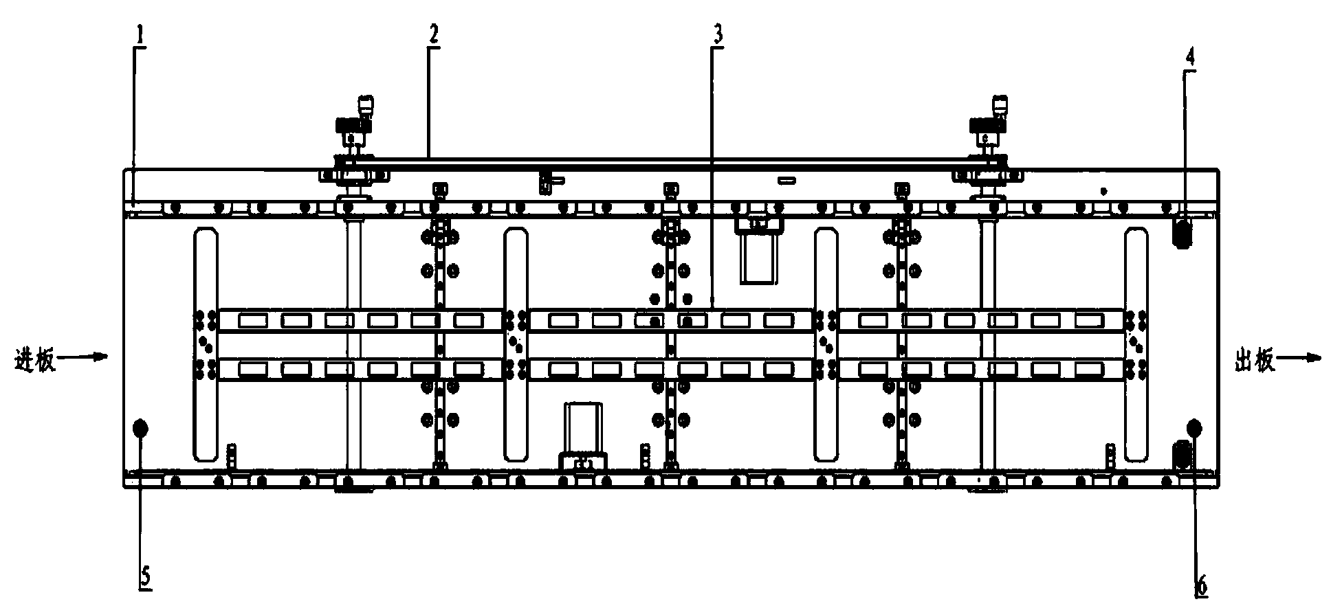
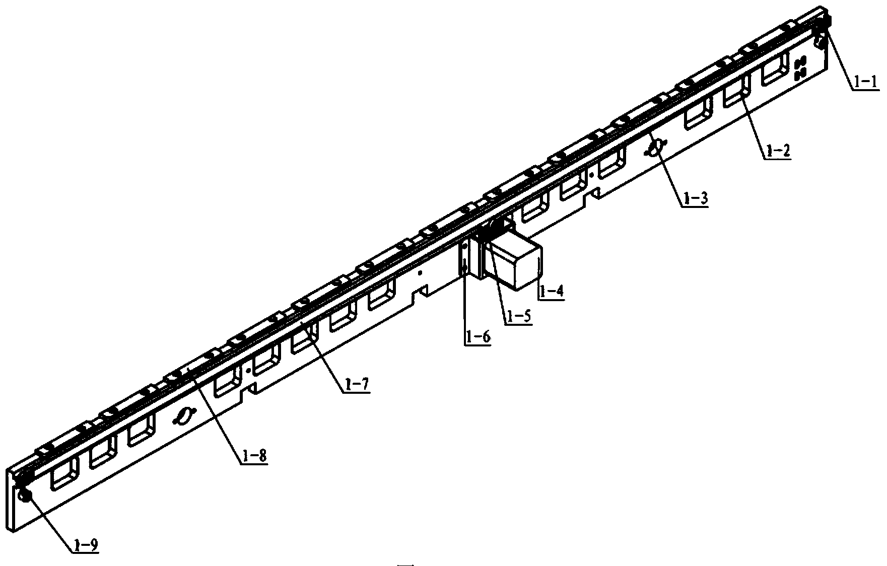
[0039] Such as Figure 1 to Figure 5 As shown, an automatic board feeding device for an LED placement machine of the present invention includes a PCB width adjustment mechanism 2, a PCB conveying mechanism 1, a PCB top plate mechanism 3 and a PCB positioning mechanism 4; the PCB width adjustment mechanism 2 is arranged on the PCB top plate mechanism 3 on both sides, the PCB conveying mechanism 1 is set on the PCB width adjusting mechanism 2, and the PCB positioning mechanism 4 is set on the output end of the PCB width adjusting mechanism 2;

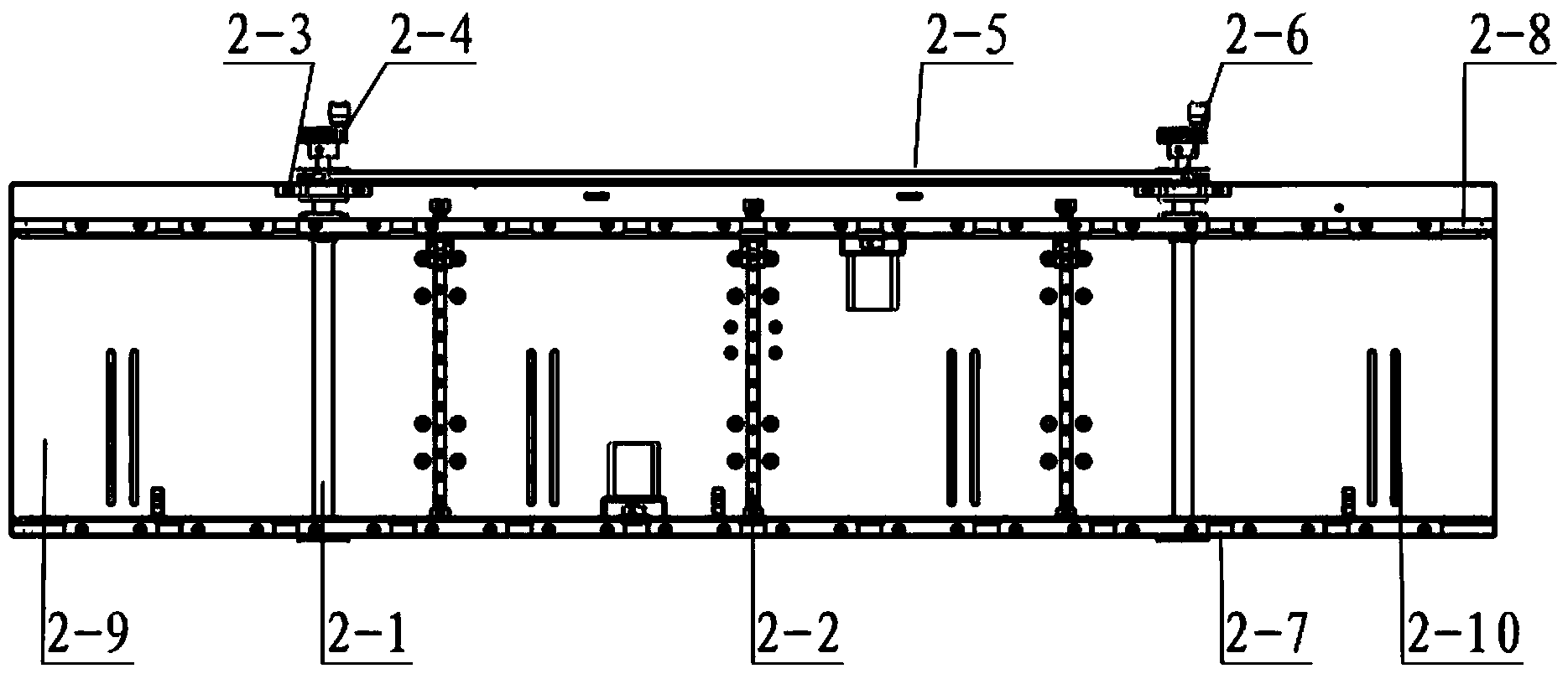
[0040] The PCB width adjustment mechanism 2 includes a fixed side plate 2-8, a movable side plate 2-7, a guide rail 2-2, a bottom plate 2-9 and at least two screw rods 2-1, the fixed side plate 2-8 and The guide rail 2-2 is installed on the base plate 2-9, the moving side plate 2-7 is installed on the guide rail 2-2, and the fixed side plate 2-8 and the moving side plate 2-7 are connected by a screw rod 2-1 ; The screw mandrel 2-1 is equ...


PUM


Abstract

The invention discloses an automatic plate feeding device of an LED chip mounter. The device comprises PCB conveying mechanisms, PCB width adjusting mechanisms, a PCB top plate mechanism and PCB positioning mechanisms, wherein the PCB width adjusting mechanisms are arranged at the two sides of the PCB top plate mechanism; the PCB conveying mechanisms are arranged on the PCB width adjusting mechanisms; and the PCB positioning mechanisms are arranged at plate discharge ends of the PCB width adjusting mechanisms. The device is simple in structure, is conveniently operated, can realize such functions of PCB automatic transmission, automatic clamping and automatic positioning, saves the labor cost, can form a full-automatic LED production line through the fitting of all procedures, and effectively improves the production efficiency.

Description

technical field [0001] The invention belongs to the field of conveying equipment, in particular to an automatic board feeding device applied to an LED placement machine for conveying PCBs. Background technique [0002] At present, with the development of modern electronic components in the direction of miniaturization, integration and high reliability, in the face of increasingly fierce market competition, the production and manufacturing equipment of electronic products are moving towards high-speed, high-precision, intelligent, The development of multi-functional and other fully automated directions, especially the assembly of printed boards for key components in electronic information products needs to be produced through the placement process. In recent years, with the development of the LED industry, new challenges have been brought to the overall performance of LED placement machines. Most of the mainstream LED placement machines in the market currently use manual clam...

Claims


Application Information

Patent Timeline
Patent Type & Authority Applications(China)
IPC IPC(8): B65H5/02
Inventor 潘兵孙继斌毕世书孙鹏宋睿冯宝林叶晓东骆敏舟
Owner CHANGZHOU INST OF ADVANCED MFG TECH
Why Eureka
Try Eureka