Junction structure of bare concrete shear wall and inner filler wall and implementation method thereof

A technology of fair-faced concrete and shear wall, applied in the direction of building structure, wall, building components, etc., can solve the problems of affecting the appearance quality of fair-faced concrete surface, expanding the tie net, weakening the overall error, etc., to achieve flatness and appearance quality. The effect of reducing construction pollution and saving repair costs

Active Publication Date: 2015-03-04
JIANGSU NANTONG SANJIAN CONSTRUCTION GROUP CO LTD
View PDF5 Cites 3 Cited by
  • Summary
  • Abstract
  • Description
  • Claims
  • Application Information

AI Technical Summary

Problems solved by technology

However, the inner filling wall needs to be plastered. In order to prevent the cracking of the plastering at the junction of different bases (concrete shear wall and filling wall) due to the different deformation coefficients of the base material of the wall, the usual practice is to use two bases at the junction. Paste the tension mesh on the surface, such as alkali-resistant fiber mesh cloth, metal mesh, etc., and then plaster the surface to cover the tension mesh. This method creates a problem. Paste the tension mesh and its surface plastering layer After completion, the paste area will protrude from the fair-faced concrete shear surface, which will affect the flatness of the fair-faced concrete shear wall surface
In order to eliminate this effect, the current practice is to expand the plastering width on the surface of the mesh, so that the overall error of the pasted area protruding from the concrete surface is weakened, but this treatment method will affect the quality of the surface of the fair-faced concrete.

Method used


Image

  • Junction structure of bare concrete shear wall and inner filler wall and implementation method thereof
  • Junction structure of bare concrete shear wall and inner filler wall and implementation method thereof
  • Junction structure of bare concrete shear wall and inner filler wall and implementation method thereof

Examples


Embodiment 1

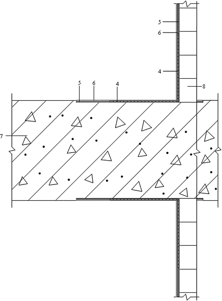
[0020] Such as figure 1 As shown, the structure at the junction of the clear-water concrete shear wall and the inner filling wall includes the clear-water concrete shear wall 7 and the inner filling wall 8. The two sides of the shear wall 7 are concave at the vertical junction with the inner filling wall 8, forming a Shaped concave surface, the concave surface is bonded to the inner filling wall 8 after the base plastering through alkali-resistant glass fiber mesh cloth 4 and plain cement slurry 5 mixed with 108 glue (amount of 20%), and mixed with 108 glue (amount of 15%) %) of 1:2 cement slurry 6 for surface plastering, and the part of the shear wall 7 located on the concave surface is plastered with cement slurry 6 and the surface is at the same level as the rest of the surface.

Embodiment approach

[0021] The implementation method of above-mentioned structure, comprises the following steps:

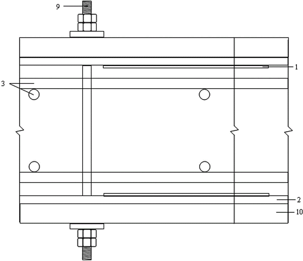
[0022] (1) Use bamboo plywood 2 with a thickness of 9mm to make a shear wall formwork, such as figure 2 As shown, the reinforcement mesh 3 is installed inside the formwork, the two sides of the formwork are tightened with pull bolts 9, the formwork is externally fixed with section steel supports 10, and the inner wall of the formwork is located at the vertical intersection of the shear wall 7 and the inner filling wall 8. Fix the rectangular shape with self-tapping wood screws Steel plate 1; wherein, the thickness of the rectangular steel plate 1 is 2.5 mm, its length is the length of the junction of the shear wall 7 and the inner filling wall 8, and its width is 300 mm+thickness of the inner filling wall 8;

[0023] (2) Pour fair-faced concrete into the formwork, and form a shear wall 7 after forming and removing the formwork. The surface of the shear wall 7 is located at the rect...

Embodiment 2

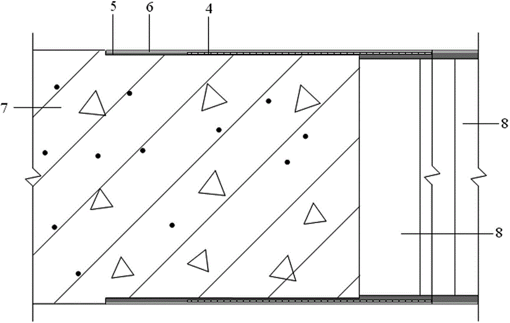
[0027] Such as image 3 As shown, the structure at the junction of the fair-faced concrete shear wall and the inner filling wall includes the fair-faced concrete shear wall 7 and the inner filling wall 8, and the shear wall 7 is concave on both sides of the horizontal junction with the inner filling wall 8, forming strip Shaped concave surface, the concave surface is bonded to the inner filling wall 8 after the base plastering through alkali-resistant glass fiber mesh cloth 4 and plain cement slurry 5 mixed with 108 glue (amount of 20%), and mixed with 108 glue (amount of 15%) %) of 1:2 cement slurry 6 for surface plastering, and the part of the shear wall 7 located on the concave surface is plastered with cement slurry 6 and the surface is at the same level as the rest of the surface.

[0028] The implementation method of above-mentioned structure, comprises the following steps:

[0029] (1) Use bamboo plywood 2 with a thickness of 9 mm to make a shear wall formwork, such as...


PUM

PropertyMeasurementUnit
Thicknessaaaaaaaaaa
Widthaaaaaaaaaa
Thicknessaaaaaaaaaa

Abstract

The invention discloses a junction structure of a bare concrete shear wall and an inner filler wall. The structure comprises the dry concrete shear wall and the inner filler wall, wherein the two sides of the junction where shear wall is vertically or horizontally connected with the inner filler wall are sunk inwards to form bar-shaped concave surfaces; the concave surfaces are conglutinated to the inner filler wall through an alkali-resistant glass fiber gridding fabric and plain grout; the base layer of the inner filler wall is plastered; the surface layer is plastered by grout; after the surface layers of the parts, positioned on the concave surfaces, of the shear wall are plastered by the grout, the surfaces of the other parts are on the same horizontal surface. The structure has the advantages that after the structure is adopted, plastering on the place where the shear wall and the inner filler wall are connected is not easy to crack; due to the fact that the shear wall has a bare concrete effect, plastering is not required, materials are saved, construction pollution is reduced, and repairing cost is also saved; meanwhile, the flatness and observation quality of the surface of a wall body are better.

Description

technical field [0001] The invention relates to a building structure, in particular to the junction structure of a clear-faced concrete shear wall and an inner filling wall and an implementation method thereof. Background technique [0002] For buildings with frame shear wall structure, if the shear wall achieves the effect of fair-faced concrete, the plastering can be canceled, which can save materials, reduce construction pollution, and avoid disputes caused by common problems of plastering quality. This saves on rework costs. However, the inner filling wall needs to be plastered. In order to prevent the cracking of the plastering at the junction of different bases (concrete shear wall and filling wall) due to the different deformation coefficients of the base material of the wall, the usual practice is to use two bases at the junction. Paste the tension mesh on the surface, such as alkali-resistant fiber mesh cloth, metal mesh, etc., and then plaster the surface to cover...

Claims


Application Information

Patent Timeline
IPC IPC(8): E04B2/56E04G21/00
Inventor 魏勇金振宇杜勇施卫德许芬陆建兵陈杨汤生黄正杰
Owner JIANGSU NANTONG SANJIAN CONSTRUCTION GROUP CO LTD
Why Eureka
Try Eureka