
C0 complexity and correlation coefficient-based milling chatter detection method

A technology of correlation coefficient and detection method, applied in measuring devices, measuring/indicating equipment, measuring ultrasonic/sonic/infrasonic waves, etc., can solve the problems of time-consuming calculation, poor robustness, sensitivity to changes in working conditions, etc., and achieve a small amount of calculation. , the effect of good accuracy and high sensitivity

Active Publication Date: 2015-03-04
XI AN JIAOTONG UNIV
View PDF4 Cites 17 Cited by
  • Summary
  • Abstract
  • Description
  • Claims
  • Application Information

AI Technical Summary

Problems solved by technology

There are two problems in using traditional chatter detection methods to detect chatter: 1) The establishment of traditional chatter detection indicators is not completely based on signal components reflecting chatter, so it will be affected by components that are not related to chatter. Most of the indicators are dimensioned indicators, which are sensitive to changes in working conditions; 2) Existing nonlinear indicators such as permutation entropy, approximate entropy, Lyapunt index, etc. need to reconstruct the phase space of the signal, and the calculation is time-consuming and less robust. In addition, the choice of embedding dimension during phase space reconstruction has a great influence on the result

Method used


Image

  • C0 complexity and correlation coefficient-based milling chatter detection method
  • C0 complexity and correlation coefficient-based milling chatter detection method
  • C0 complexity and correlation coefficient-based milling chatter detection method

Examples


Embodiment Construction

[0039] The present invention will be further described in detail below in conjunction with the accompanying drawings and specific embodiments.

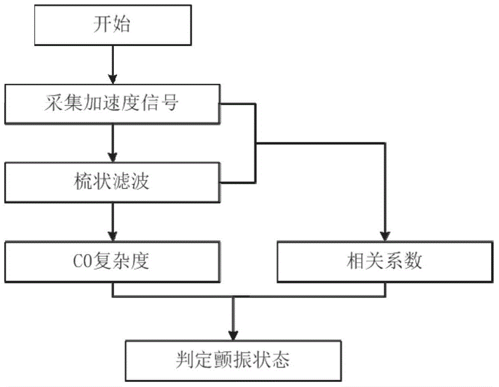
[0040] refer to figure 1 , the present invention is based on C 0 The milling chatter detection method of complexity and correlation coefficient comprises the following steps:

[0041] 1) Acquisition of signal:

[0042] Vibration information during milling is collected through a vibration acceleration sensor (sensitivity of 10.09mv / g) arranged at the end of the high-speed spindle, and the obtained signal is expressed as X=[x(1),x(2),…,x(n)] , n represents the signal length.

[0043] 2) Comb filtering of the signal:

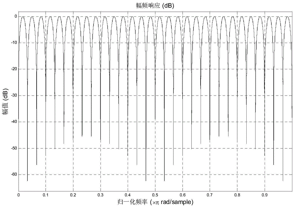
[0044] The transfer function of the comb filter system is where N is the filter order, (N is an integer), f s is the sampling frequency (Hz), is the frequency to be filtered out (Hz), Ω is the spindle speed (r / min), and a is a constant between 0 and 1. When a increases, the filter frequency response curve is fl...


PUM


Abstract

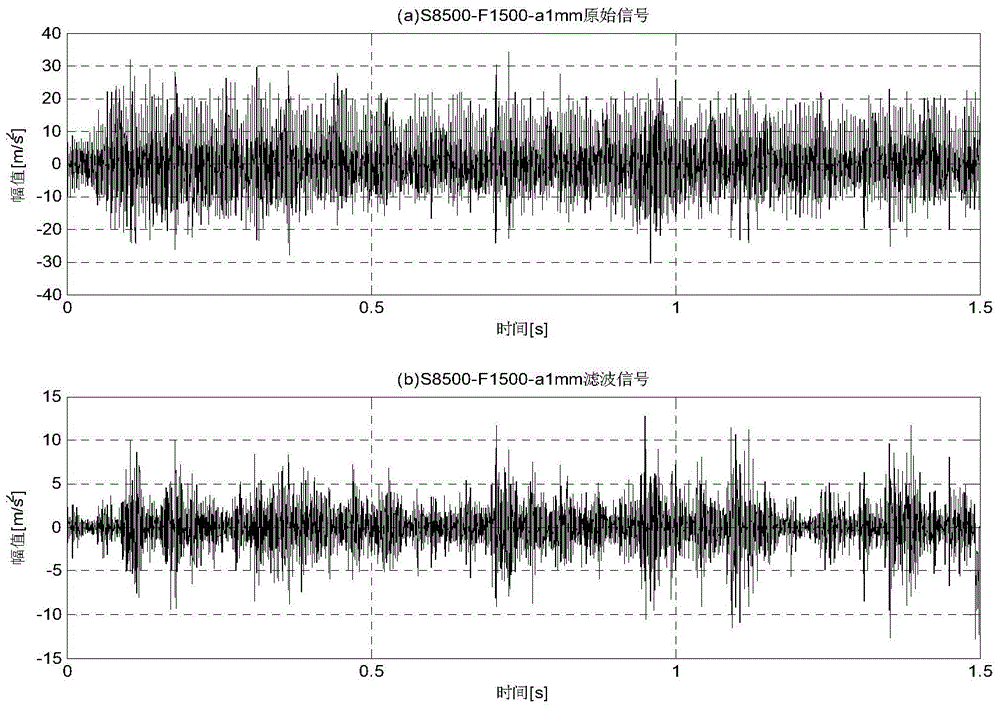
The invention discloses a C0 complexity and correlation coefficient-based milling chatter detection method. The C0 complexity and correlation coefficient-based milling chatter detection method includes the following steps that: state information of a milling process is obtained through a vibration acceleration sensor; obtained signals are preprocessed through using a comb filter, so that periodic components can be filtered out; the complexity of residual signals is calculated through utilizing C0 complexity indexes, so that the degree of nonlinearity of chatter can be reflected; and the correlation coefficient of original signals and filtered signals is calculated, and therefore, the proportion of chatter components in the signals can be reflected, and chatter degree in the machining process can be described. Compared with a traditional chatter detection method, and according to the C0 complexity and correlation coefficient-based milling chatter detection method of the invention, characteristic information reflecting chatter and characteristic information irrelevant to chatter are separated out from each other, and various kinds of indexes are fused, and physical characteristics of milling chatter can be essentially characterized. With the C0 complexity and correlation coefficient-based milling chatter detection method adopted, the sensitivity, accuracy and reliability of chatter detection can be effectively improved, and misdiagnosis rate and missed diagnosis rate can be decreased.

Description

technical field [0001] The invention relates to a mechanical processing state monitoring technology, in particular to a detection method for milling chatter of a high-speed milling machine. Background technique [0002] Milling technology has the advantages of high production efficiency, high processing accuracy and low processing cost, and is widely used in aviation, aerospace, mold, automobile and other manufacturing fields. Making full use of the advantages of advanced manufacturing technology largely depends on the ability to predict and control abnormal vibration phenomena (such as cutting chatter) in the milling process. During the milling process, due to the unreasonable selection of processing parameters, severe vibrations often occur between the tool and the workpiece, resulting in chatter. Chatter is a strong self-excited vibration between the tool and the workpiece in the metal cutting process. The occurrence of chatter not only reduces the surface quality and di...

Claims


Application Information

Patent Timeline
IPC IPC(8): G01H17/00B23Q17/12
Inventor 曹宏瑞周凯訾艳阳陈雪峰成玮张兴武
Owner XI AN JIAOTONG UNIV
Learn More