L1/2-norm-based sparse linear array optimization method

A linear array, L1 norm technology, used in electrical digital data processing, special data processing applications, instruments, etc., can solve the problems of not meeting the constraints of the array aperture, dense arrays, and large array apertures.

Active Publication Date: 2015-03-04
NANJING UNIV OF INFORMATION SCI & TECH
View PDF3 Cites 21 Cited by
  • Summary
  • Abstract
  • Description
  • Claims
  • Application Information

AI Technical Summary

Problems solved by technology

However, it has two major disadvantages: first, in order to avoid the appearance of grating lobes, the distance between array elements is usually not greater than half of the wavelength. If the wavelength is small, the array will be too dense and cause serious mutual coupling between array elements; If the array has a higher resolution, the aperture of the array will be very large, and more array eleme

Method used


Image

  • L1/2-norm-based sparse linear array optimization method
  • L1/2-norm-based sparse linear array optimization method
  • L1/2-norm-based sparse linear array optimization method

Examples


Embodiment 1

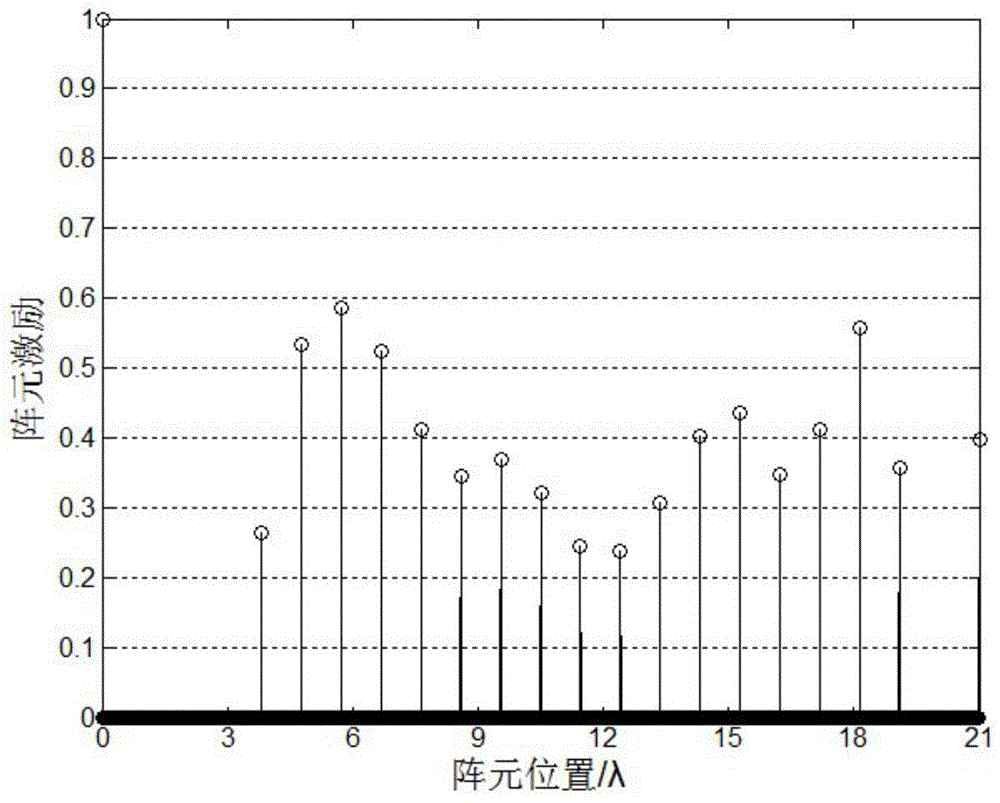
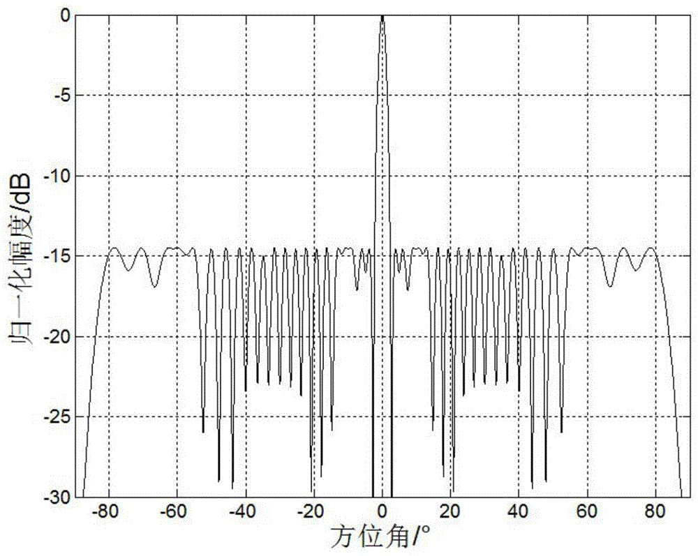
[0068] Under the condition that the main lobe width is 4.6°, the peak side lobe level is less than -14.49dB, and the array aperture is 21λ, the sparse linear array is optimized. Firstly, Giancarlo Prisco and Michele D’Urso based on iterative weighted L 1 The norm array optimization method optimizes the array, and the distance d between adjacent array elements is set to 0.01λ, so the initial number of array elements is 2101. After optimization, the array element positions and excitation value distribution of the sparse array are as follows: figure 2 as shown, image 3 Its corresponding beam pattern; then adopt the method of the present invention to optimize the array, the distance d between adjacent array elements is set to 0.1λ, and the initial array element distribution is set to be looser, so the calculation amount during optimization can be reduced; Figure 4 The array element position and excitation value distribution diagram of the sparse array optimized for the method ...

Embodiment 2

[0070] Under the condition that the main lobe width is 4°, the peak side lobe level is less than -30dB, and the array aperture is 50λ, the 192 -Based on iterative weighted L proposed in the paper on page 195 1 The array optimization method of the norm and the method of the present invention perform sparse linear array optimization respectively; under the same condition of initializing the array, that is, the distance d between adjacent array elements is set to 0.1λ, based on the iterative weighted L 1 The simulation results of array optimization using norm array optimization method are as follows: Figure 6 shown by Figure 6 It can be seen that the sparse linear array optimized by this method will have the absence of the first and last array elements, so it does not meet the given array aperture length condition; considering that any element in the array weight vector may be zero during the optimization process, in order to satisfy the given For a given array aperture lengt...


PUM


Abstract

The invention relates to an L1/2-norm-based sparse linear array optimization method. The method is characterized by comprising the basic steps of determining an initial array and a weighting matrix, determining array weight vectors, judging whether the stimulus of head and tail array elements in the array weight vector is greater than a set stimulus minimum delta or not, judging whether an L1 norm for optimizing a difference between the previous and latter array weight vectors is smaller than a set error minimum xi or not, and determining the array element positions and stimulus of the sparse linear array. According to the method, the non-convex optimization problem of solution to an L1/2 norm is converted into a series of convex optimization problems of the L1 norm, so that a sparse array with lower sparsity can be obtained to reduce the number of actually required array elements on the premise of substantially keeping calculation unchanged; meanwhile, the head and tail array elements of the array are constrained and adaptively regulated under the condition of given array aperture, so that the problem of deficiency of the head and tail array elements of the sparse array in an iterative convex optimization process is well solved, and the method is particularly applied to the place of optimization of a large-sized antenna array.

Description

technical field [0001] The invention belongs to the technical field of antenna array optimization, in particular to an L-based 1 / 2 A sparse linear array optimization method for norm. Background technique [0002] In radar, communication, sonar, ultrasonic imaging and other electronic systems, in order to make the antenna beam have strong directivity, low sidelobe, easy scanning and other performance indicators, antenna arrays have been widely used, and the optimal design of antenna arrays has become a modern electronic system. A very important link in the design. In the early research of antenna arrays, evenly spaced arrays have been extensively studied due to their simple design, convenient mathematical processing, and ease of implementation. However, it has two major disadvantages: first, in order to avoid the appearance of grating lobes, the distance between array elements is usually not greater than half of the wavelength. If the wavelength is small, the array will be ...

Claims


Application Information

Patent Timeline
IPC IPC(8): G06F17/50
Inventor 陈金立曹华松李家强葛俊祥
Owner NANJING UNIV OF INFORMATION SCI & TECH
Why Eureka
Try Eureka