Undervoltage release

A voltage and external power grid technology, applied in the direction of protection switch operation/release mechanism, etc., can solve problems such as undervoltage release misoperation, circuit breaker false opening, imperfection, etc., to avoid harmonic interference and reliable pull-in , the effect of small calorific value

Inactive Publication Date: 2015-03-04
CHANGZHOU INST OF TECH
View PDF4 Cites 2 Cited by
  • Summary
  • Abstract
  • Description
  • Claims
  • Application Information

AI Technical Summary

Problems solved by technology

[0005] The circuit design of the existing undervoltage release is mostly simple or imperfect. In the occasions where the interference is serious, especially the circuit breaker near the intermediate frequency application occasion, the undervoltage release is often interfered by the intermediate frequency and malfunctions.
Or when the frequency of the marine generator changes, the undervoltage release will malfunction due to the frequency change
The misoperation of the undervoltage release caused the misopening of the circuit breaker

Method used


Image

  • Undervoltage release
  • Undervoltage release

Examples


Embodiment 1

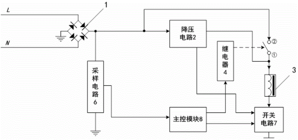
[0028] See figure 1 , an undervoltage release, comprising: a rectifier circuit 1 connected to an external power grid, an electromagnet coil 3, an armature controlled by the electromagnet coil 3; a step-down circuit 2, the input terminal of which is connected to the rectifier circuit 1 The positive output terminal of the relay 4 is connected with the current input terminal of the electromagnet coil 3, and its output terminal is connected with the current input terminal of the electromagnet coil 3, so as to provide a voltage for maintaining the armature pull-in; The output terminal is connected to the current input terminal of the electromagnet coil 3; the switch circuit 7 is connected to the current input terminal of the electromagnet coil 3; the sampling circuit 6 is used to detect the output pulsation of the rectifier circuit 1 DC voltage value; the main control module 8 stores the rated voltage Ue and the voltage value of the strong start, and is used to collect the output v...

Embodiment 2

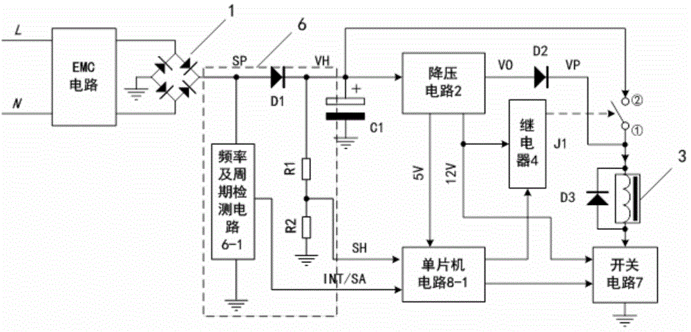
[0036] See Figure 1-2 , on the basis of Example 1, the implementation of the main part of the undervoltage release is described.

[0037] The full-wave pulsating voltage is isolated by the isolation diode D1 from the voltage VH charged to the strong start-up capacitor C1 without affecting the pulsating voltage SP. The VH voltage is stepped down by a step-down circuit 2 to provide working power for the relay 4 and the switch circuit 7 of the main control module 8. The voltage VO formed by the step-down circuit 2 is isolated by the diode D2 and the voltage VP is the electromagnet coil. 3 power supply. The resistors R1 and R2 form a sampling circuit of VH, and the sampling signal SH is sent to the main control module 8 . The pulsating voltage after full-wave rectification, frequency and period detection circuit 6-1 forms INT / SA signal, the main control module 8 analyzes the INT signal to obtain the grid cycle time (frequency), samples SA several times in one cycle, and applies...

Embodiment 3

[0045] See Figure 1-2 On the basis of the embodiment 1-2, taking 220V voltage and the main control module 8 using the single-chip microcomputer circuit 8-1 as an example, the implementation mode of the main part of the anti-harmonic and full-frequency undervoltage release is described.

[0046] The grid voltage is connected to the two input ends of the rectification circuit 1 after EMC bidirectional filtering. The positive end of the rectification circuit 1 is defined as (VH), and the negative end is grounded (GND).

[0047] After power-on, the rectifier circuit 1 rectifies the AC voltage into a DC pulsating voltage SP, charges the strong start-up capacitor C1 through the isolation diode D1, and the charging voltage VH is equal to the input AC voltage times (80% effective value, approximately equal to 248V). The charging voltage has a voltage sampling circuit 6 composed of R1 and R2 in series, and the production sampling signal SH is sent to the single-chip microcomputer. ...


PUM


Abstract

The invention relates to an undervoltage release. The undervoltage release comprises a rectifying circuit connected with external power grid, an electromagnet coil, an armature controlled by the electromagnet coil, a voltage dropping circuit, a relay, a sampling circuit, a main control module which is stored with a rated voltage value Ue and a voltage value of forced startup; the main control module is used for collecting an output voltage and a voltage cycle of the sampling circuit in order to calculate an effective voltage value of the external power grid and a pulse direct current voltage value; when the voltage of the external power grid reaches 80% of the rated voltage Ue, and the pulse direct current voltage reaches the voltage value of forced startup, a normally open contact is controlled to close firstly, and then a switch circuit is controlled to switch on, and the normally open contact is controlled to open after the armature is engaged; if the voltage of the external power grid is less than 50% of the rated voltage Ue, the switch circuit is controlled to switch off. The undervoltage release is reliable in engagement, low in coil calorific value, strong in anti-interference capacity, and is applicable to frequency conversion occasions such as a generator.

Description

[0001] This application is a divisional application of the invention patent application with the application number 201210225139.7, the application date is July 2, 2012, and the invention name is "an undervoltage release and its working method". technical field [0002] The invention relates to a low-power undervoltage release and its working method. Background technique [0003] The undervoltage release is one of the important components of circuit breakers, especially frame circuit breakers. The undervoltage release is a release that makes the circuit breaker disconnect with or without delay when its terminal voltage drops to a certain range. When the power supply voltage drops (even slowly) to the rated operating Within the range of 70% to 35% of the voltage, the undervoltage release should act (the coil of the release is de-energized, and the movable armature in the coil is pushed out by the return spring—tripping), and the undervoltage release will trip when the power s...

Claims


Application Information

Patent Timeline
Patent Type & Authority Applications(China)
IPC IPC(8): H01H71/24
CPCH01H71/24
Inventor 吴志祥
Owner CHANGZHOU INST OF TECH
Why Eureka
Try Eureka