
LED (Light Emitting Diode) color temperature regulating chip and application circuit thereof

A color temperature and chip technology, which is applied in the field of color temperature chip circuits, can solve the problems of too many devices and cost pressures, and achieve the effects of simplifying peripheral devices, saving costs, and saving production

Active Publication Date: 2015-03-04
WUXI SI POWER MICRO ELECTRONICS
View PDF4 Cites 4 Cited by
  • Summary
  • Abstract
  • Description
  • Claims
  • Application Information

AI Technical Summary

Problems solved by technology

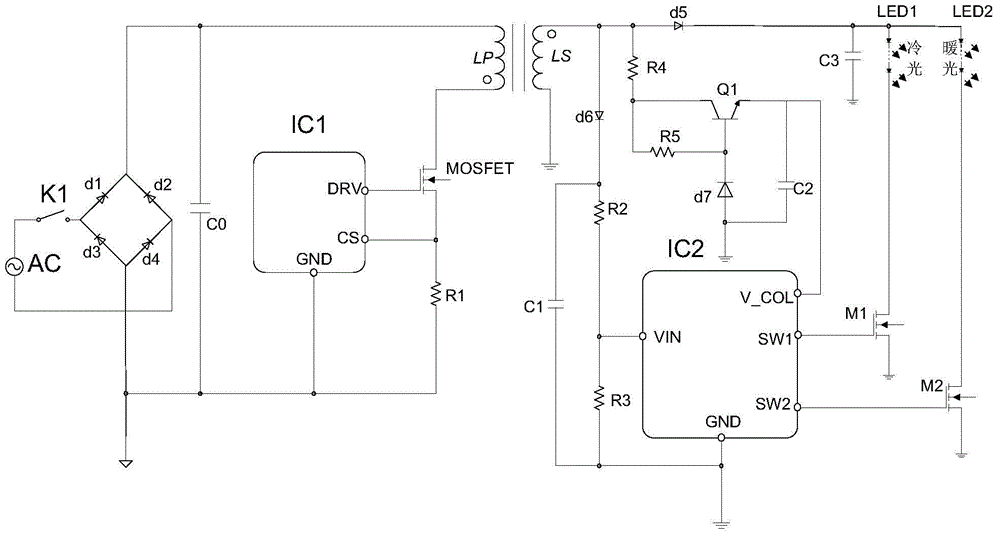
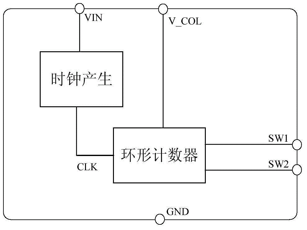
[0006] However, the disadvantage of this dimming circuit is the cost. The color temperature chip IC2 must cooperate with many peripheral devices to realize the function of color temperature. There are still too many devices for the detection part of VIN and the external regulated power supply part of V_COL. put some pressure on the cost of the whole program

Method used


Image

  • LED (Light Emitting Diode) color temperature regulating chip and application circuit thereof
  • LED (Light Emitting Diode) color temperature regulating chip and application circuit thereof
  • LED (Light Emitting Diode) color temperature regulating chip and application circuit thereof

Examples


Embodiment Construction

[0038] The present invention will be further described below in conjunction with specific drawings and embodiments.

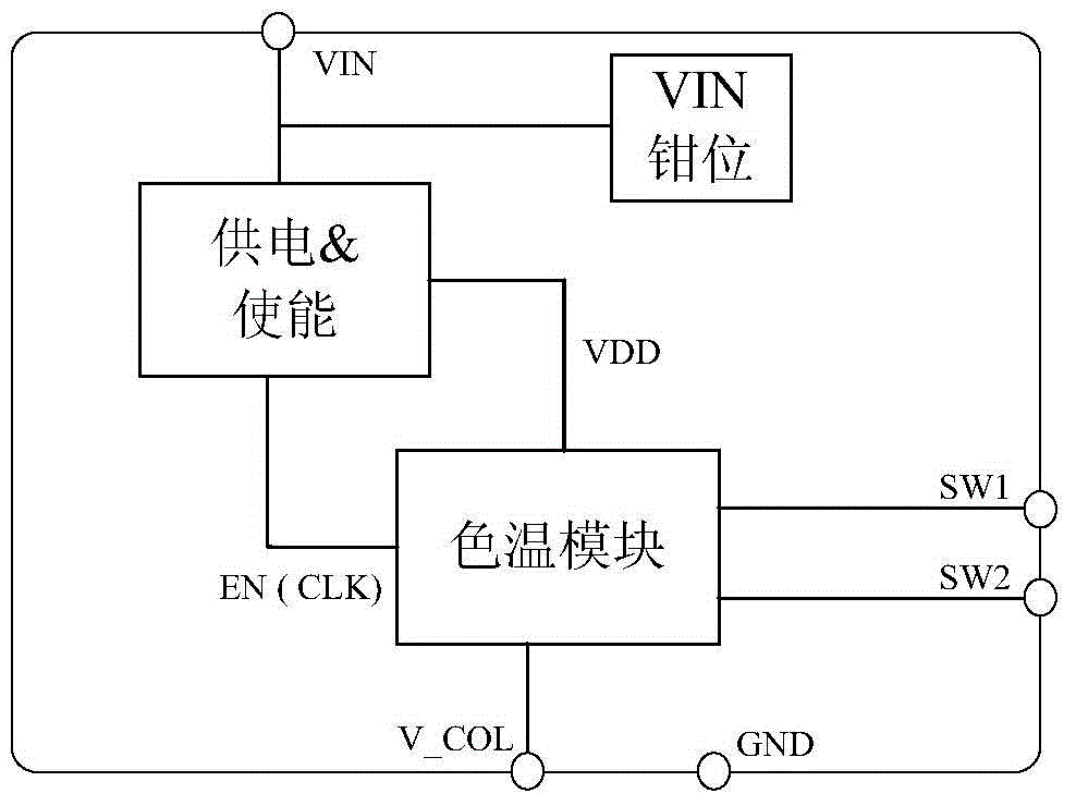
[0039] The following will combine Figure 3A Specifically explain the present invention, Figure 3A It is a schematic diagram of the internal frame of the LED color temperature chip shown in the present invention. The chip includes:

[0040] The clamping module is used to keep the chip power supply terminal VIN at the clamping voltage; the color temperature chip can work at a higher voltage or withstand a short-term high-voltage impact without damage. In this example, the clamping module can keep the voltage of the chip power terminal VIN at about 15-20v.

[0041] The power supply and enable module, whose input terminal is connected to the chip power supply terminal VIN, is used to generate the clock CLK, that is, the enable signal EN, and provide the internal low-voltage power supply VDD of the chip; the low voltage here means that it is supplied to the col...


PUM


Abstract

The invention provides an LED (Light Emitting Diode) color temperature regulating chip. The LED color temperature regulating chip comprises a clamping module, a power supply and enabling module and a color temperature module; the clamping module is used for enabling the chip power supply end VIN to be maintained at the clamping voltage; an input end of the power supply and enabling module is connected with the chip power supply end VIN and used for generating clock namely enabling signals EN and providing a chip internal low voltage power supply VDD; the input of the color temperature module is the enabling signals EN; the power is supplied for the color temperature module through the chip internal low voltage power supply VDD; the color temperature module is connected with a second power supply end V_COL and two control ends SW1 and SW2 of the chip; the color temperature module is used for enabling the high level to be output from the two control ends SW1 and SW2 in turn. According to the LED color temperature regulating chip, the internal structure is simple and reasonable, only a few peripheral devices are required by the application scheme, the cost is low, the application range is wide, and the LED color temperature regulating chip can be applied to multiple structures of LED driving circuits.

Description

technical field [0001] The invention relates to an LED drive circuit, in particular to a color temperature chip circuit. Background technique [0002] With the rapid development of LED technology, LED lighting has entered thousands of households, and people have higher and higher requirements for the experience of using LED lights. For example, people want to use cool color light when it is hot, and people want to use warm color light when it is cold. This is the LED color temperature. The early color temperature solution was realized by using MCU, but the cost of the solution was relatively high. In the prior art, it is typical to realize the color temperature by designing a special color temperature chip and cooperating with corresponding peripheral devices. Therefore, how to design an LED color temperature solution that satisfies users while controlling costs has become a trend in the development of LED color temperature technology. [0003] figure 1 It is a simplifie...

Claims


Application Information

Patent Timeline
IPC IPC(8): H05B37/02
Inventor 涂才根黄飞明赵文遐励晔吴霖朱勤为
Owner WUXI SI POWER MICRO ELECTRONICS
Learn More