Measuring and controlling device for on-demand micro drop injection process based on image processing and measuring and controlling method thereof
An on-demand micro, image processing technology, applied in the field of on-demand jet printing, can solve the problems of time-consuming and labor-intensive metal micro-droplet jetting device, the inability to ensure the stability of the jetting process in real time, and the difficulty in meeting precise control requirements, etc., to avoid Time-consuming and labor-intensive, avoiding the effect of low accuracy
- Summary
- Abstract
- Description
- Claims
- Application Information
AI Technical Summary
Problems solved by technology
Method used
Image
Examples
specific Embodiment approach 1
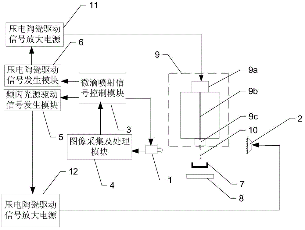
[0031] Specific implementation mode one: combine figure 1 Describe this embodiment, the measurement and control device of the on-demand droplet ejection process based on image processing described in this embodiment, the device includes a camera 1, a strobe light source 2, a droplet ejection signal control module 3, image acquisition and Processing module 4, frequency light source drive signal generation module 5, piezoelectric ceramic drive signal generation module 6, piezoelectric ceramic drive signal amplification power supply 11 and frequency light source drive signal amplification power supply 12;
[0032] The photographing device 1 and the stroboscopic light source 2 are placed on the same level as the nozzle 9c of the metal droplet ejection device 9, and the photographing device 1 is controlled by the droplet ejection signal control module 3 to shoot the metal droplets sprayed by the nozzle 9c, and the stroboscopic light The source 2 is used for the background light whe...
specific Embodiment approach 2
[0039] Specific embodiment 2: This embodiment is the measurement and control method of the measurement and control device of the on-demand micro-droplet ejection process based on image processing described in the specific embodiment 1. Before the metal micro-droplet ejection device 9 starts to perform droplet ejection, the The molten metal recovery device moves to directly below the nozzle 9c; after the metal material to be printed is heated to the set temperature and kept warm in the on-demand metal droplet ejection device 9, the following method is started;
[0040] The method comprises the steps of:
[0041] Step 1: The droplet ejection signal control module 3 controls the piezoelectric ceramic drive signal generation module 6 to drive the piezoelectric ceramic transducer 9a with the set initial piezoelectric ceramic drive signal to generate axial stretching vibration; at the same time, control the stroboscopic light source drive signal The generating module 5 sends a strob...
Embodiment
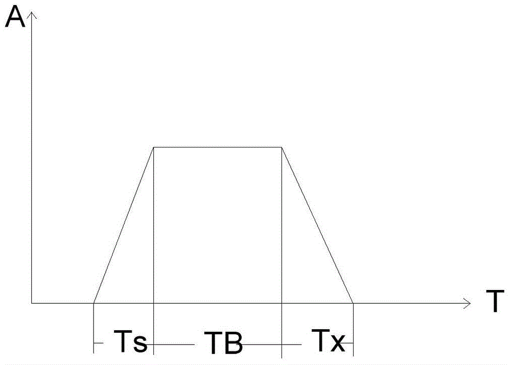
[0058] In order to obtain a stable micro-droplet ejection process that meets the deposition requirements, the mechanical vibration process generated by the piezoelectric ceramic transducer 9a under the action of the driving waveform signal is very important. The present invention adopts the trapezoidal wave as the drive signal waveform of the piezoelectric ceramic transducer, such as image 3 . The driving trapezoidal wave is divided into three parts according to the driving effect: the Ts stage is the stage where the piezoelectric ceramic transducer is deformed under the action of the signal to drive the vibrator to push out. This stage is the stage where the micro-droplets are forced to eject from the nozzle. The length of Ts affects the injection speed; Tb is that the waveform signal reaches the amplitude and remains stationary, so the vibrator also remains at rest for a certain period of time. At this time, the molten metal continues to be ejected with inertia, and this st...
PUM
 Abstract
Description
Claims
Application Information
 - R&D
- Intellectual Property
- Life Sciences
- Materials
- Tech Scout
- Unparalleled Data Quality
- Higher Quality Content
- 60% Fewer Hallucinations
Browse by: Latest US Patents, China's latest patents, Technical Efficacy Thesaurus, Application Domain, Technology Topic, Popular Technical Reports.
© 2025 PatSnap. All rights reserved.Legal|Privacy policy|Modern Slavery Act Transparency Statement|Sitemap|About US| Contact US: help@patsnap.com


