Deep hole boring cutter

A deep hole boring tool and tool body technology, which is applied in the direction of cutting blades, accessories of tool holders, and tools used in lathes, etc., can solve the problem of uneven force on the cutting edge and extrusion edge, increasing the difficulty of tool sharpening, and cutting tools Expensive manufacturing costs and other issues to achieve the effect of preventing chips and coolant from splashing around, reducing the overall weight of the tool, and facilitating disassembly and installation

Inactive Publication Date: 2015-03-11
CHONGQING YAOYONG SHOCK ABSORBER
View PDF6 Cites 2 Cited by
  • Summary
  • Abstract
  • Description
  • Claims
  • Application Information

AI Technical Summary

Problems solved by technology

However, due to the design problem of the original structure of the boring tool, the tool is bulky, the tool manufacturing cost is expensive, the service life is low, and the processing quality is unstable, such as figure 1 As shown in , the boring tool is installed on the spindle of the machine tool through the Morse taper shank. Due to the heavy weight of the tool, the centrifugal force generated during the rotation of the spindle is likely to cause uneven force on the cutting edge and extrusion edge, thus making the surface roughness of the boring hole unstable
Moreover, the self-weight of the tool is too heavy, which is extremely inconvenient when sharpening the tool, which increases the difficulty of tool sharpening; the length of the tool will also greatly restrict the types of tools that can be processed; because the chip flute is an outer chip flute structure, the machining process is caused by the rotation of the tool. Chips and coolant splash around with the rotation of the tool, resulting in wet and slippery working bottom surface, increasing the risk of working

Method used


Image

  • Deep hole boring cutter
  • Deep hole boring cutter
  • Deep hole boring cutter

Examples


Embodiment Construction

[0031] The implementation of the present invention will be illustrated by specific specific examples below, and those skilled in the art can easily understand other advantages and effects of the present invention from the contents disclosed in this specification.

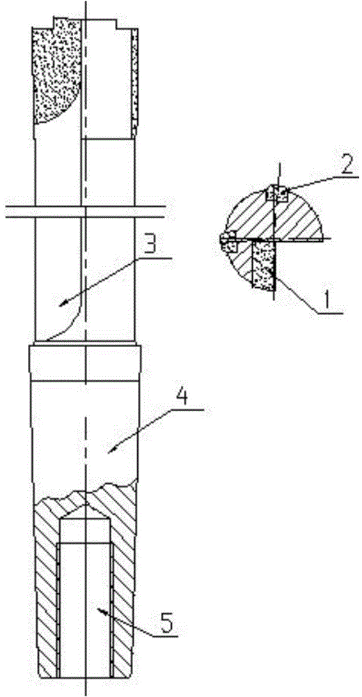
[0032] Such as figure 1 As shown, the traditional boring tool is installed on the spindle of the machine tool through the Morse taper shank 4, the workpiece is fixed on the tooling, the spindle drives the tool to rotate, and the workpiece is fed along the guide rail to complete the boring process. The specific operation process is as follows: the excess material is cut off by the cutting edge 1, and then the machined surface is squeezed by the extrusion edge 2, and the chips are discharged through the chip discharge groove 3.

[0033] Due to the heavy weight of the tool, the centrifugal force generated during the rotation of the spindle is likely to cause uneven force on the cutting edge 1 and the extrusion edge 2, ...


PUM


Abstract

The invention provides a deep hole boring cutter. The deep hole boring cutter comprises a cutter body and a cutter rod; a chip hole is formed in the center of the cutter body; the cutter rod is of a hollow structure and is in threaded connection with the rear end of the cutter body; a cutting blade is arranged at the front end of the cutter body; a chip groove is formed in the cutter body part at one side of the cutting blade, and the chip groove is communicated with the chip hole. According to the deep hole boring cutter, a working part is an independent part according to the design, namely, an individual cutter body, and therefore, the weight of the cutter body can be greatly reduced, and an edge can be conveniently grinded; the external chip removal structure is replaced by an internal chip removal structure according to the design, which prevents the chips and cooling liquid produced in processing from splashing all around; the threaded connecting structure enables convenient dismounting and mounting of the cutter body, and thus the cutter can be conveniently grinded and adjusted during use; the hollow cutter rod is used, so that the weight of the whole cutter is reduced, and an hole in the cutter rod can be fully utilized for removing chips; the processing procedure can be modified to control the feeding length of the cutter rod to be adapted to the processing of different deep holes.

Description

technical field [0001] The invention relates to the technical field of cutting tools, in particular to a deep hole boring tool. Background technique [0002] With the intensification of production tasks and the gradual increase in the export volume of foreign trade products, the surface roughness quality of the deep hole of the shock absorber bottom tube needs to be improved urgently, and the requirements for boring tools for deep hole processing are also getting higher and higher. However, due to the design problem of the original structure of the boring tool, the tool is bulky, the tool manufacturing cost is expensive, the service life is low, and the processing quality is unstable, such as figure 1 As shown in , the boring tool is installed on the spindle of the machine tool through the Morse taper shank. Due to the heavy weight of the tool, the centrifugal force generated during the rotation of the spindle is likely to cause uneven force on the cutting edge and extrusion...

Claims


Application Information

Patent Timeline
Patent Type & Authority Applications(China)
IPC IPC(8): B23B27/00
CPCB23B27/00B23B2200/328
Inventor 黄强李耀勇谭庆洪张杰田祥云翁长江周明元杨志明
Owner CHONGQING YAOYONG SHOCK ABSORBER
Why Eureka
Try Eureka