A pneumatic nut removal device
What is Al technical title?
Al technical title is built by PatSnap Al team. It summarizes the technical point description of the patent document.
A nut and nut mechanism technology, applied in metal processing, metal processing equipment, manufacturing tools, etc., can solve the problems of reducing the work efficiency of workers, heavy quality, high labor intensity, etc., to avoid random swing, easy to operate, and improve efficiency. Effect
Inactive Publication Date: 2016-08-24
TONGXIANG SHENGHUI PRECISION MACHINERY
View PDF6 Cites 0 Cited by
Summary
Abstract
Description
Claims
Application Information
AI Technical Summary
This helps you quickly interpret patents by identifying the three key elements:
Problems solved by technology
Method used
Benefits of technology
Problems solved by technology
[0002] Using compressed air as the power source, the device used to disassemble the nut is a pneumatic tool. Its power source is the compressed air output by the air compressor. When the compressed air enters the cylinder, it drives the impeller inside to rotate to generate rotational power. The impeller then drives the connected striking part to carry out hammering-like transportation. After each striking, the nut is tightened or loosened. It is an efficient and safe tool for disassembling and assembling nuts, but the existing pneumatic disassembling The nut device is an integrated pneumatic tool. It has a complex structure, large volume, and heavy weight. When disassembling the nut, the worker needs to hold the nut dismounting tool to disassemble the nut. The labor intensity of the worker is relatively high. The work efficiency of workers is low, and it is very laborious in the operation process. It is difficult for workers to carry out long-term work, especially when disassembling some large nuts, it is necessary to use some larger tools for disassembling nuts. Low, and due to the need to disassemble the nut, it is necessary to frequently move the pneumatic nut disassembly device, which reduces the work efficiency of the workers and cannot meet the needs of production
Method used
Image
Click on the blue label to locate the original text in one second.
Reading with bidirectional positioning of images and text.
Examples
Embodiment Construction
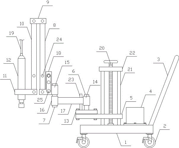
[0010] In order to further describe the present invention, a specific implementation of a pneumatic nut removal device will be further described below in conjunction with the accompanying drawings. The following examples are explanations of the present invention and the present invention is not limited to the following examples.
[0011] Such as figure 1 As shown, a pneumatic nut removal device of the present invention includes a base 1 and a nut removal mechanism, and the nut removal mechanism is arranged on the base 1 . The lower side of the base 1 of the present invention is evenly provided with a plurality of universal wheels 2 with brakes, one side of the base 1 is obliquely provided with a trolley handle 3, the upper side of the base 1 is horizontally provided with a nut storage box 4, and the dismounting nut mechanism is arranged on the nut On one side of the storage box 4, a plurality of universal wheels with brakes evenly arranged on the lower side of the base can be ...
PUM
Abstract
The invention relates to a pneumatic nut detachment and installation device, and belongs to the field of mechanical processing equipment. The pneumatic nut detachment and installation device comprises a base and a nut detachment and installation mechanism, wherein the nut detachment and installation mechanism is arranged on the base, a plurality of universal wheels with brakes are uniformly arranged at the lower side of the base, a handcart handle is obliquely arranged at one side of the base, a nut storage box is horizontally arranged at the upper side of the base, the nut detachment and installation mechanism comprises a lifting plate, a fixing shaft, a rotary shaft, a first connecting plate, a second connecting plate, a third connecting plate, a fourth connecting plate and a nut detachment and installation machine head, the lifting plate is horizontally arranged on the base, a lifting mechanism is vertically arranged at one side of the lifting plate, the fixing shaft is vertically arranged on a fixing plate, the rotary shaft is vertically arranged at one side of the fixing shaft, the nut detachment and installation machine head is vertically, downwards and fixedly arranged on the fourth connecting plate, and an air-intake duct is arranged at the upper end of the nut detachment and installation machine head. The pneumatic nut detachment and installation device has the advantages that the structure is simple, the operation is convenient, a nut can be detached and installed in a high-speed and high-efficiency way, the labor intensity of workers is decreased, and the production requirements are met.
Description
technical field [0001] The invention relates to a nut dismounting device, in particular to a pneumatic nut dismounting device, which belongs to the field of mechanical processing equipment. Background technique [0002] Using compressed air as the power source, the device used to disassemble the nut is a pneumatic tool. Its power source is the compressed air output by the air compressor. When the compressed air enters the cylinder, it drives the impeller inside to rotate to generate rotational power. The impeller then drives the connected striking part to carry out hammering-like transportation. After each striking, the nut is tightened or loosened. It is an efficient and safe tool for disassembling and assembling nuts, but the existing pneumatic disassembling The nut device is an integrated pneumatic tool. It has a complex structure, large volume, and heavy weight. When disassembling the nut, the worker needs to hold the nut dismounting tool to disassemble the nut. The labo...
Claims
Application Information
Patent Timeline
Application Date:The date an application was filed.
Publication Date:The date a patent or application was officially published.
First Publication Date:The earliest publication date of a patent with the same application number.
Issue Date:Publication date of the patent grant document.
PCT Entry Date:The Entry date of PCT National Phase.
Estimated Expiry Date:The statutory expiry date of a patent right according to the Patent Law, and it is the longest term of protection that the patent right can achieve without the termination of the patent right due to other reasons(Term extension factor has been taken into account ).
Invalid Date:Actual expiry date is based on effective date or publication date of legal transaction data of invalid patent.