
Dual-pulse hydraulic oscillator for well drilling

A hydraulic oscillator and double-pulse technology, applied in vibratory drilling, etc., can solve problems such as single function, poor continuous working ability, and poor oscillation effect

Inactive Publication Date: 2015-03-11
YANGTZE UNIVERSITY
View PDF7 Cites 46 Cited by
  • Summary
  • Abstract
  • Description
  • Claims
  • Application Information

AI Technical Summary

Problems solved by technology

[0004] The purpose of the present invention is to provide a common drill bit and drilling tool assembly that can be used at a small flow rate to generate relatively high frequency and large axial vibrations, effectively reducing the frictional resistance of the drilling tool assembly during drilling; The high-frequency vibration can produce an effect similar to that of percussion drilling and increase the ROP; through the periodic rock breaking with soft pressure changes, the rock breaking efficiency can be improved; the existing technology has a single function, low performance and quality, and must be configured Expensive, high-performance drill bits and drill tool assemblies can only meet the impact parameter standards; limited by the structure and materials, the service life is short, and the continuous working ability is poor, resulting in many times of drilling and tripping, which seriously hinders mechanical drilling, and does not fundamentally solve the drilling problem. Double-pulse hydraulic oscillator for drilling with excessive friction resistance and poor oscillation effect

Method used


Image

  • Dual-pulse hydraulic oscillator for well drilling
  • Dual-pulse hydraulic oscillator for well drilling
  • Dual-pulse hydraulic oscillator for well drilling

Examples


Embodiment Construction

[0015] Embodiments of the present invention are described in detail below in conjunction with accompanying drawings:

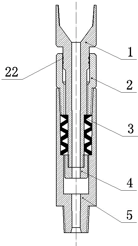
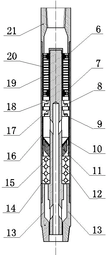
[0016] The double-pulse hydraulic oscillator for drilling is composed of a vibration sub assembly and a power sub assembly; the vibration sub assembly and the power sub assembly are connected by threads; the vibration sub assembly is connected by a spline mandrel 1, Sleeve 2, pressure converter 3, compression nut 4, and oscillating housing 5; the upper end of the spline mandrel 1 is connected to the drill pipe through threads, and a seal 22 is installed between the spline mandrel 1 and the coupling sleeve 2, and the spline The mandrel 1 is slidingly connected to the inner wall of the coupling sleeve 2; the coupling sleeve 2 is connected to the oscillating housing 5 through threads; the pressure converter 3 is installed between the lower end of the spline mandrel 1 and the oscillating housing 5; that is, the pressure converter 3 is installed on the flower In th...


PUM


Abstract

The invention relates to a dual-pulse hydraulic oscillator for well drilling, and belongs to the technical fields of petroleum and natural gas exploration and well drilling tools. The dual-pulse hydraulic oscillator consists of an oscillation short section assembly and a power short section assembly, and is characterized in that the oscillation short section assembly consists of a spline mandrel, a connection sleeve, a pressure converter, an oscillation shell and the like; the power short section assembly comprises a pressing sleeve and a turbine shaft; a sealing piece is mounted between the spline mandrel and the connection sleeve; the connection sleeve is connected with the oscillation shell; the lower end of the turbine shaft is connected with the power short section assembly; the pressing sleeve at the upper end of the power short section assembly is connected with the oscillation shell; the lower end of the pressing sleeve is connected with a power shell; the turbine shaft is mounted at the center of the power shell; a straightening bearing, a turbine stator, a turbine rotor, two groups of movable valves and fixed valves, a sleeve, a flow division ring, a flow division sleeve and a thrust bearing are mounted on the turbine shaft in sequence from top to bottom. Radial swinging is avoided; under low flow, higher axial vibration with higher frequency can be realized; the friction resistance is low, so that effective drilling pressure is increased, and the mechanical drilling speed is increased.

Description

technical field [0001] The invention relates to a double-pulse hydraulic oscillator for drilling, which belongs to the technical field of oil and natural gas exploitation and drilling tools. Background technique [0002] During the drilling process, the important factor affecting the penetration rate of extended reach wells and horizontal wells is frictional resistance. During sliding drilling, the drilling tool assembly and the borehole wall are in a state of static friction, and the frictional resistance is relatively large, which may easily cause drilling back pressure or sticking, seriously affecting the drilling process, especially for horizontal wells. With the continuous deepening of exploration and development, extended-reach horizontal wells and wells with complex conditions are gradually increasing. How to reduce frictional resistance, reduce back pressure in sliding drilling, increase effective WOB, and improve the efficiency of conventional drilling, Chinese rese...

Claims


Application Information

Patent Timeline
IPC IPC(8): E21B7/24
CPCE21B7/24
Inventor 冯定孙巧雷鄢标夏成宇施雷
Owner YANGTZE UNIVERSITY
Learn More