Roof-contacted method for mine gob-side entry paste filling wall body

A technology of paste filling and roadway retention, which is applied to filling materials, mining equipment, earth cube drilling and mining, etc. It can solve the problems of cumbersome operation, long support time and damage of filling body, etc., and achieve simple operation procedures and low filling cost Effect

Inactive Publication Date: 2015-03-11
SHANDONG UNIV OF SCI & TECH
View PDF9 Cites 10 Cited by
  • Summary
  • Abstract
  • Description
  • Claims
  • Application Information

AI Technical Summary

Problems solved by technology

Relatively speaking, the paste filling material is currently the most commonly used filling material for gob-side entry retention due to its high initial strength, long support time, and low cost. However, it cannot be effectively connected to the roof during the filling process, making the top surface of the wall There is a gap between the roof and the roof, which will not only cause the working face to sink sideways to the roof, impact and damage the filling body, but also easily lead to air leakage in the goaf and spontaneous combustion of coal in the goaf
[0003] In order to solve the roofing problem of roadside filling and goaf retention, Chinese Patent Publication No. CN101792291A discloses a high water expansion material. The expansion rate of this material can reach 10-30%. The expansion rate of the material causes the inside of the filling body to be honeycomb-shaped after the material is solidified, and the strength is greatly reduced. When the roof sinks too much, it is easy to cause the filling body to be damaged, and it cannot effectively support the overlying rock

Method used


Image

  • Roof-contacted method for mine gob-side entry paste filling wall body
  • Roof-contacted method for mine gob-side entry paste filling wall body
  • Roof-contacted method for mine gob-side entry paste filling wall body

Examples


Embodiment Construction

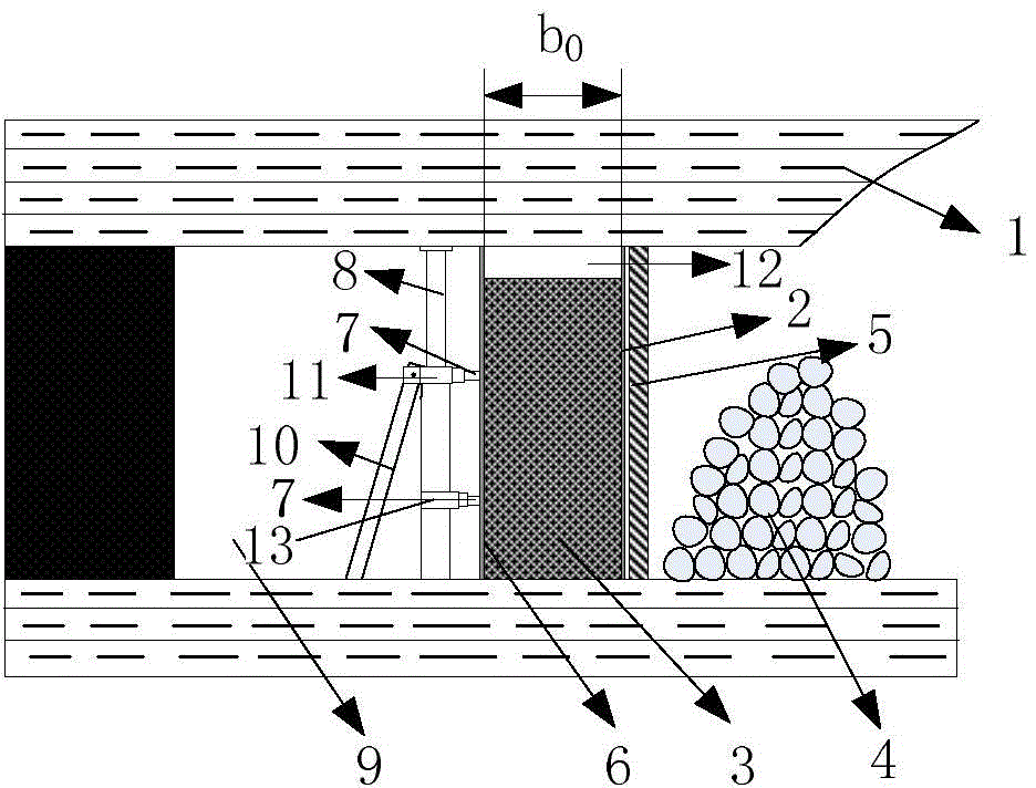
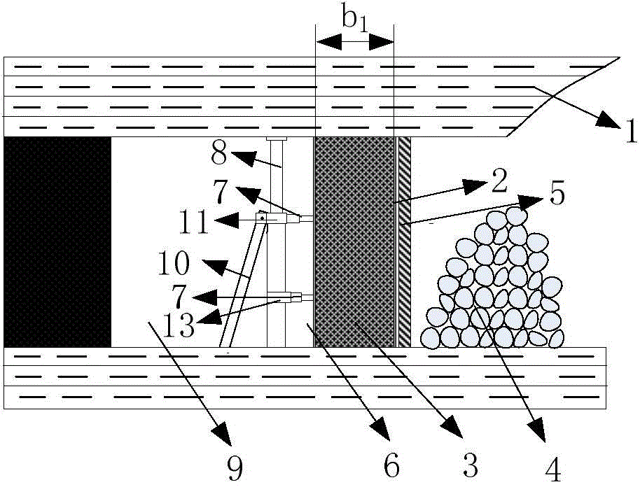
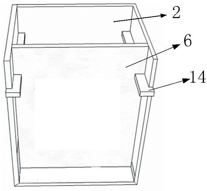
[0023] like Figure 1 ~ Figure 3 As shown in the figure, a method for side push and roof connection of gob-side filling and gob-side entry retaining, the specific steps are:

[0024] 1. First calculate the erection width b of the filling formwork 0 , the width is the design width b of the filling body 1 Add the reduction value Δh of the width after pressing the filling body to the top; b 0 =b 1 +Δh

[0025] Δh can be calculated according to the principle that the volume of the filling body does not change before and after the top is connected. The formula is as follows:

[0026] Δh=b 0 -b 1 =b 1 / η-b 1

[0027] In the formula: η—filling rate;

[0028] 2. When the coal seam in the pre-filled section of the working face is mined for one working cycle and the frame is moved, a row of wooden pillars 5 with a spacing of 0.8m should be supported on the side of the pre-filled section near the goaf in time, and the spacing between the other sections should be installed. It ...


PUM


Abstract

The invention discloses a roof-contacted method for a mine gob-side entry paste filling wall body. The roof-contacted method mainly comprises the following steps: installing a filling template according to a filling design width in a gob or roadway of a pre-filling section, and filling the filling template with a prepared paste-like filling material by using a filling pump; when the height of the filling material reaches 85%-90% of actual filling height, pushing the filling template through pressure of a jack, so that the filling material inside the filling template moves forward and is extruded to rise, after the filling material rises to contact a roof, maintaining the pressure of the jack, moving forward, extruding to rise the filling material, and after the filling material rises to contact the roof, maintaining the pressure of the jack until the filling material is finally solidified. Horizontal thrust is applied before the filling material is solidified, so that the width of a filling body is contracted and the height of the filling body is increased until the filling material is roof-contacted with the top plate of the roadway, and after the filling material is solidified, a gap formed between the wall body and the top plate is completely eliminated, so that the air leakage of the gob is avoided, and the self-combustion of coal is prevented.

Description

technical field [0001] The invention relates to a coal pillar-free mining technology in a coal mining face in a mine, in particular to a gob-side filling and entry retaining technology in a coal mining face in a mine. Background technique [0002] At present, roadside filling and gob-side entry retention is a pillar-free mining technology commonly used in mines at home and abroad. Usually, high-water materials, concrete and paste materials are used as roadside filling materials, and pre-proportioned filling materials are injected into In the filling formwork, the filling material solidifies and supports the lateral roof of the roadway, and retains the roadway to serve the working face of the next section. The implementation of gob-side entry retention technology can not only improve the recovery rate of coal resources and reduce production costs, but also help prevent major disasters such as mine rock burst, coal and gas outburst, and achieve sustainable development of mines...

Claims


Application Information

Patent Timeline
IPC IPC(8): E21F15/00
CPCE21F15/00
Inventor 宁建国王俊李学慧史新帅胡昊
Owner SHANDONG UNIV OF SCI & TECH
Why Eureka
Try Eureka