Display panel and display device
A display panel and display substrate technology, which is applied in the directions of identification devices, instruments, optics, etc., can solve the problems of increased overall thickness of the display panel, decreased image display brightness, light loss, etc., to improve display effect, reduce loss rate, and improve restoration degree of effect
- Summary
- Abstract
- Description
- Claims
- Application Information
AI Technical Summary
Problems solved by technology
Method used
Image
Examples
Embodiment 1
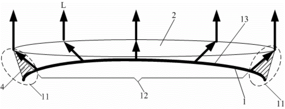
[0030] This embodiment provides a display panel, such as figure 1 As shown, it includes a display substrate 1 and a light processing element 2 arranged on the light emitting side of the display substrate 1. The display substrate 1 includes a frame area 11 and a display area 12 surrounded by the frame area 11. The display substrate 1 is bent at least in the frame area 11, and the light processing The element 2 is at least correspondingly arranged in the frame area 11 for changing the direction of light emitted from the display substrate 1 so that the image displayed on the display area 12 can cover the frame area 11 .
[0031] In this embodiment, the display substrate 1 is curved as a whole, and the light processing element 2 corresponds to the display substrate 1 that is curved as a whole.
[0032] Among them, the display substrate 1 refers to a complete display module capable of image display, and the display substrate 1 can be any flexible and bendable image display such as ...
Embodiment 2
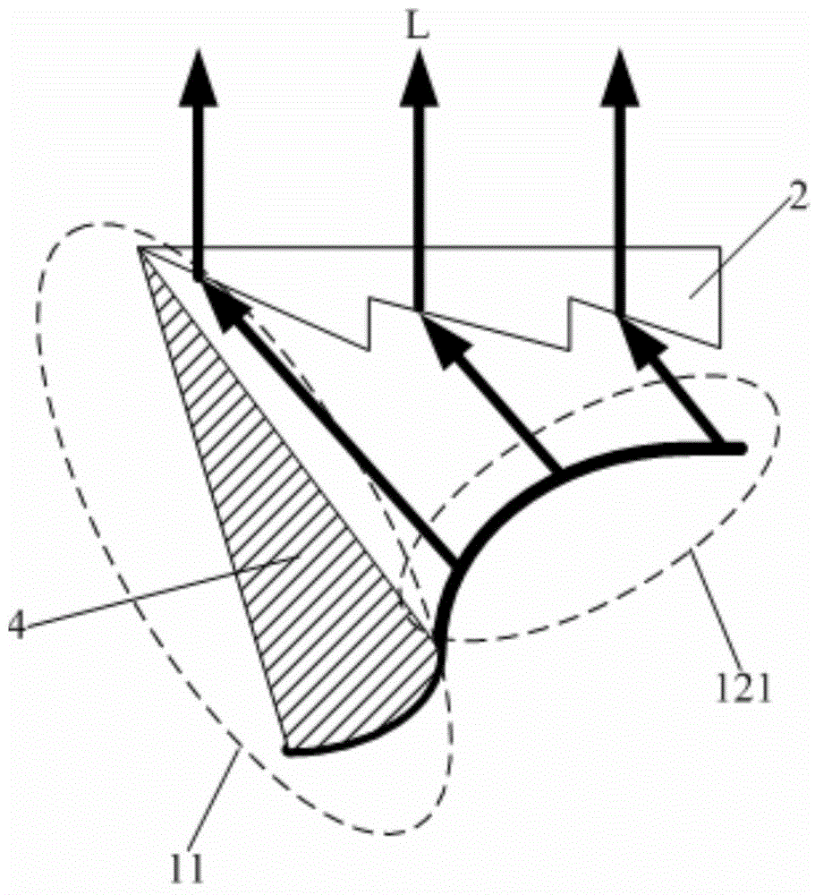
[0044] This embodiment provides a display panel. The difference from Embodiment 1 is that figure 2 with image 3 As shown, the frame area 11 is curved toward the direction opposite to the light output of the display substrate 1 to form an arc surface, the arc surface is convex in the light output direction of the display substrate 1, the display area 12 is flat, and the light processing element 2 is correspondingly arranged above the frame area 11. Prism group or convex lens. In this embodiment, the light processing element 2 is a prism group.
[0045] The frame area 11 is curved, so that the bordering edge 121 of the display area 12 and the frame area 11 can also form a certain curved arc surface. When displaying, the light emitted by the arc bordering edge 121 is emitted along the normal direction of the arc surface Therefore, the light emitted from the bordering edge 121 is divergent. Compared with the planar display substrate 1, the irradiation range of the light emitte...
Embodiment 3
[0056] This embodiment provides a display device, including the display panel in any one of Embodiments 1-2.
[0057] In this embodiment, there is one display panel, that is, a single-screen display device, and the single-screen display device can realize borderless display by using the display panel in any one of embodiments 1-2.
[0058] Certainly, there may be a plurality of display panels, and the plurality of display panels are spliced into one, so that a super large screen display formed by splicing can be realized. Since each of the display panels adopts any one of the display panels in Embodiments 1-2, no seams will appear in the entire spliced large-screen display, thereby improving the display effect of the display device.
[0059] The display device provided by the present invention may be any product or component with a display function such as a liquid crystal panel, a liquid crystal television, a monitor, an OLED panel, an OLED television, a mobile phone, and...
PUM
 Abstract
Description
Claims
Application Information
 - R&D
- Intellectual Property
- Life Sciences
- Materials
- Tech Scout
- Unparalleled Data Quality
- Higher Quality Content
- 60% Fewer Hallucinations
Browse by: Latest US Patents, China's latest patents, Technical Efficacy Thesaurus, Application Domain, Technology Topic, Popular Technical Reports.
© 2025 PatSnap. All rights reserved.Legal|Privacy policy|Modern Slavery Act Transparency Statement|Sitemap|About US| Contact US: help@patsnap.com


