Driving power source for power system fault detecting device

A fault detection and power system technology, applied in control/regulation systems, output power conversion devices, electrical components, etc., can solve problems such as large ripple coefficient, low efficiency, complex circuits, etc., to improve quality and reduce radio frequency interference , The effect of simplifying the circuit structure

Inactive Publication Date: 2015-03-11
CHENGDU CHUANGTU TECH
View PDF0 Cites 9 Cited by
  • Summary
  • Abstract
  • Description
  • Claims
  • Application Information

AI Technical Summary

Problems solved by technology

[0003] The purpose of the present invention is to overcome the defects of large ripple coefficient, serious radio frequency interference, complex circuit and low e

Method used


Image

  • Driving power source for power system fault detecting device

Examples


Embodiment

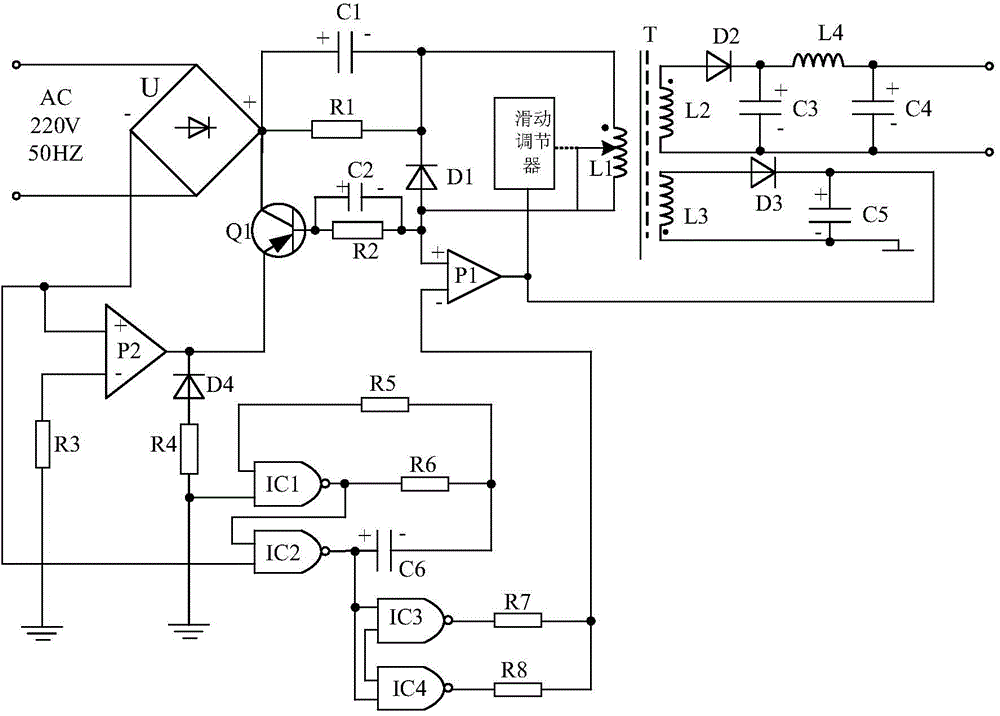
[0015] Such as figure 1 As shown, the present invention mainly consists of a diode rectifier U, a power amplifier P1, a transformer T, a switching filter circuit connected in series between the positive output terminal of the diode rectifier U and the non-inverting terminal of the power amplifier P1, and the primary side coil L1 of the transformer T The sliding regulator connected with the sliding tap of the transformer T, the power output circuit connected with the secondary coil L2 of the transformer T, the transformer feedback circuit connected with the secondary coil L3 of the transformer T, and the diode rectifier U and the switching filter circuit It is composed of a power logic regulator circuit connected with the power amplifier P1.

[0016] Wherein, the power logic regulator circuit is composed of power amplifier P2, NAND gate IC1, NAND gate IC2, NAND gate IC3, NAND gate IC4, diode D4, resistor R3, resistor R4, resistor R5, resistor R6, Composed of resistor R7, resis...


PUM


Abstract

The invention discloses a driving power source for a power system fault detecting device. The driving power source mainly comprises a diode rectifier U, a power amplifier P1, a transformer T, a switch filter circuit, a slider regulator, a power output circuit and a voltage transformation feedback circuit. The switch filter circuit is arranged between an anode output end of the diode rectifier U and a same-phase end of the power amplifier P1 in a serial connection manner, the slider regulator is connected with a sliding tap of a primary coil L1 of the transformer T, the power output circuit is connected with a secondary coil L2 of the transformer T, and the voltage transformation feedback circuit is connected with a secondary coil L3 of the transformer T. The driving power source has the advantages that high-quality input voltages can be provided for the transformer T by a novel power logic voltage stabilizing circuit, accordingly, circuit structures can be simplified, radio frequency interference of the circuits and external radio frequency interference can be reduced, and the manufacturing cost and the maintaining cost can be greatly lowered.

Description

technical field [0001] The invention relates to a switching stabilized voltage power supply, in particular to a driving power supply for a power system fault detection device. Background technique [0002] At present, with the rapid development of the power industry, the equipment that people use for power system fault detection has also developed greatly. Since the maintenance of the power system often involves voltage lines of hundreds of kilovolts or even millions of kilovolts, the maintenance lines are very long, so the power supply requirements for fault detection equipment are also very high. However, at present, the mobile power supply provided by the fault detection equipment has a large ripple coefficient, which not only produces radio frequency electromagnetic interference, but also has a complicated circuit structure, high maintenance and production costs, which largely limits The scope of use of fault detection equipment is not conducive to people's large-scale ...

Claims


Application Information

Patent Timeline
IPC IPC(8): H02M3/335
CPCH02M3/33523H02M3/33561H02M3/33576
Inventor 周鹏程
Owner CHENGDU CHUANGTU TECH
Why Eureka
Try Eureka