

Driving method of full-bridge soft switch inverter circuit
A technology of an inverter circuit and a driving method, which is applied in the direction of electrical components, high-efficiency power electronic conversion, and output power conversion devices, and can solve problems such as the complexity of the drive control of the full-bridge soft-switching inverter circuit, and achieve simple drive control and reduced Power consumption, the effect of increasing the inverter frequency
- Summary
- Abstract
- Description
- Claims
- Application Information
AI Technical Summary
Problems solved by technology
Method used
Image

Examples
no. 1 example
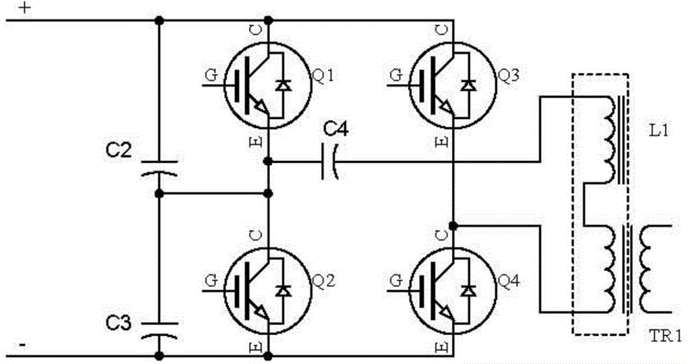
[0019] Refer below figure 1 and figure 2 Describe the hardware circuit of the full-bridge soft-switching inverter circuit of the present invention.
[0020] Such as figure 1 As shown, the full-bridge soft-switching inverter circuit includes power switching devices Q1~Q4 (IGBTs with internal diodes), main transformer TR1, external inductor L1, DC blocking capacitor C4, and absorbing capacitors C2 and C3. Among them, Q1 and Q2 are super-forearms, and Q3 and Q4 are lagging arms. As shown in the figure, the super-forearm Q1 and the lagging arm Q4 are conducted in a pair, and the super-forearm Q2 and the lagging arm Q3 are conducted in a pair.
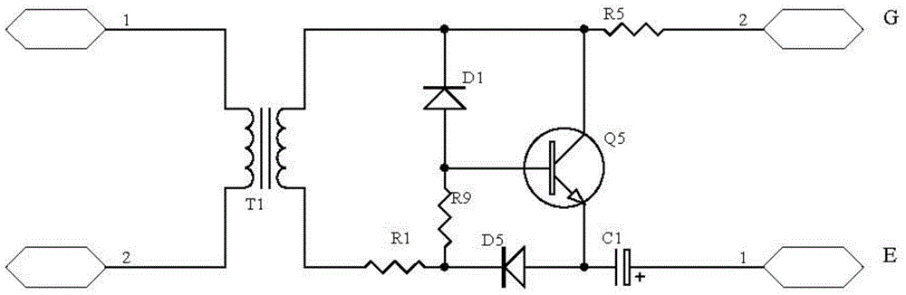
[0021] figure 2 show figure 1 The driving circuits of each power switching device in Q1-Q4 are shown. Each of Q1-Q4 is connected to the driving circuit. In this embodiment, the driving circuit is isolated by using a pulse transformer.
[0022] Below, refer to figure 2 Describe the operating principle of the drive circuit.
...
no. 2 example
[0041] Next, a second embodiment of the present invention is described.
[0042] The hardware circuit constitution of the second embodiment is exactly the same as that of the first embodiment (see figure 1 and figure 2 ), and will not be described again here. In the following, only the differences between the two are described.
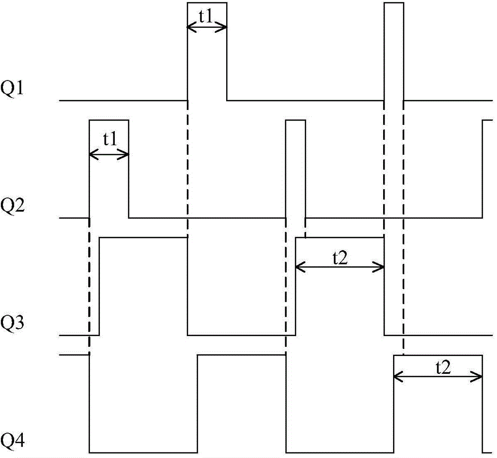
[0043] The difference between the second embodiment and the first embodiment is only that the opening of the super-forearm Q1 and the closing of the lagging arm Q3 do not occur at the same time, but the lagging arm Q3 is turned off first, and then the super-forearm Q1 is turned on. In addition, the turn-on of the super-forearm Q2 and the turn-off of the lagging arm Q4 do not occur at the same time, but the lagging arm Q4 is turned off first, and then the super-forearm Q2 is turned on (see Figure 4 ). However, it should be noted that the turn-on moments of the advanced forearms Q1 and Q2 are still within the dead time range of the lagging arms Q...
PUM
 Abstract
Description
Claims
Application Information