Pulse signal source device

A pulse signal source and signal technology, applied in the direction of electrical components, automatic power control, etc., can solve the problems of acousto-optic modulators such as large volume, high power consumption, limited laser frequency standard miniaturization and low power consumption, etc., to achieve volume Small size, low power consumption, avoiding the effect of excessive volume of laser frequency standard

Active Publication Date: 2015-03-11
恒时益博(武汉)电子科技有限公司
View PDF12 Cites 10 Cited by
  • Summary
  • Abstract
  • Description
  • Claims
  • Application Information

AI Technical Summary

Problems solved by technology

Due to the large size and high power consumption of the acousto-optic modulator, the development of

Method used


Image

  • Pulse signal source device
  • Pulse signal source device
  • Pulse signal source device

Examples


Embodiment

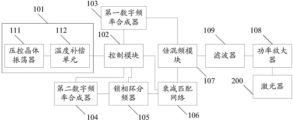
[0037] An embodiment of the present invention provides a pulse signal source device, see figure 1 , the device consists of:

[0038] an initial signal source 101, configured to output a frequency signal;

[0039] The control module 102 is configured to receive the frequency signal output by the initial signal source 101, generate a reference signal according to the frequency signal, and generate a key frequency modulation signal and a timing control signal;

[0040] The first digital frequency synthesizer 103 is used to use the reference signal generated by the control module 102 as a reference, and use the keyed frequency modulation signal generated by the control module 102 to perform keyed frequency modulation to generate a modulated signal;

[0041] The second digital frequency synthesizer 104 is used to generate an original pulse signal under the control of the timing control signal generated by the control module 102;

[0042] The phase-locked loop frequency divider 10...


PUM


Abstract

The invention discloses a pulse signal source device, and belongs to the field of atomic frequency standards. The device comprises an initial signal source, a control module, a first digital frequency synthesizer, a second digital frequency synthesizer, a phase-looed loop frequency divider, an attenuation matching network, a frequency multiplying and mixing module and a power amplifier. The initial signal source is used for outputting frequency signals; the control module is used for generating reference signals according to the frequency signals, generating keying frequency-modulated signals and generating time sequence control signals by taking the frequency signals as reference; the first digital frequency synthesizer is used for taking the reference signals as reference, performing keying frequency modulation by the keying frequency-modulated signals and generating modulating signals; the second digital frequency synthesizer is used for generating original pulse signals under the control of the time sequence control signals; the phase-locked loop frequency divider is used for processing the original pulse signals by set fractional frequency and outputting pulse signals; the attenuation matching network is used for compensating the pulse signals; the frequency multiplying and mixing module is used for frequency multiplying and mixing of the pulse signals and the modulating signals to acquire optical-detection resonance signals; the power amplifier is used for power amplification of the optical-detection resonance signals.

Description

technical field [0001] The invention relates to the field of atomic frequency standards, in particular to a pulse signal source device. Background technique [0002] The laser frequency standard is a high-precision device that locks the laser frequency to the stable transition frequency between the hyperfine energy levels of atoms or molecules, thereby obtaining high-precision laser frequency output. [0003] The existing laser frequency standards mainly include semiconductor lasers, acousto-optic modulators, physical parts and electronic circuits. Due to the large size and high power consumption of the acousto-optic modulator, the development of laser frequency standards in the direction of miniaturization and low power consumption is limited. Contents of the invention [0004] In order to solve the problems in the prior art, an embodiment of the present invention provides a pulse signal source device. Described technical scheme is as follows: [0005] An embodiment of...

Claims


Application Information

Patent Timeline
IPC IPC(8): H03L7/18
Inventor 詹志明
Owner 恒时益博(武汉)电子科技有限公司
Why Eureka
Try Eureka