Code grouping smart remote control lamp circuit

A remote control lamp and circuit technology, which is applied in the direction of electric lamp circuit layout, energy-saving control technology, electric light source, etc., can solve the problems of changing working status, short life of mechanical switches, easy failures, etc., to avoid serial code interference, facilitate product promotion, The effect of enhancing attractiveness

Inactive Publication Date: 2015-03-11
唐世福
View PDF2 Cites 12 Cited by
  • Summary
  • Abstract
  • Description
  • Claims
  • Application Information

AI Technical Summary

Problems solved by technology

Some traditional similar products, such as solar lights, save power and save data by turning off the lights at regular intervals to shorten the working time. However, data will still be lost in the case of insufficient charging on continuous cloudy days, and the utilization rate of battery capacity will be reduced. ; Some products use mechanical switches to switch and lock the working state of the lamp,

Method used


Image

  • Code grouping smart remote control lamp circuit
  • Code grouping smart remote control lamp circuit

Examples


Embodiment Construction

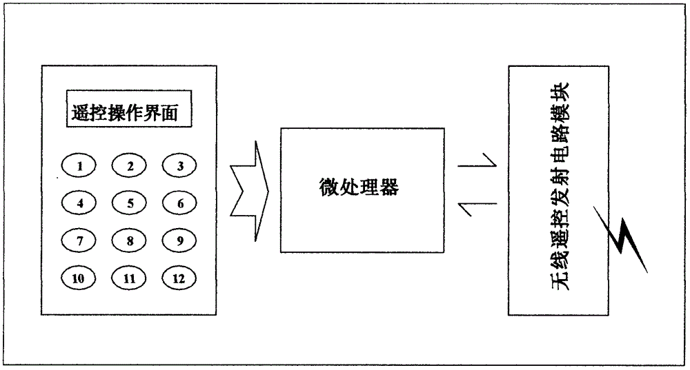
[0015] attached figure 1 It is a structural block diagram of the remote control transmitter of the present invention

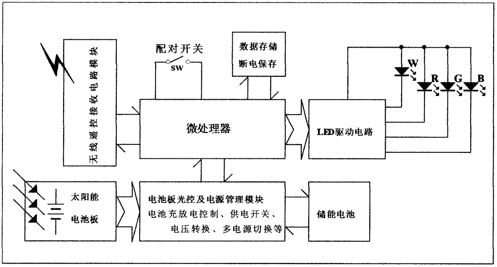
[0016] attached figure 2 It is a block diagram of remote control reception and control structure of the present invention

[0017] For the convenience of explanation, the remote controller described below represents the remote control transmitting circuit, and the solar lamp represents the remote control receiving and controlling circuit.

[0018] Below at first illustrate the composition and the function of each part circuit of the present invention:

[0019] attached figure 1 Among them, the circuit is composed of three parts, the key operation interface, the processor and the signal transmitting circuit. After the user presses the function key of the remote control, the processor will process the corresponding key code and combine it with the unique address code of the processor to form a remote control code, and the coded signal will be sent out in th...


PUM


Abstract

The invention provides a novel code grouping smart remote control lamp circuit. The code grouping smart remote control lamp circuit is mainly composed of a remote control transmission circuit with a code grouping module and a plurality of remote control receiving circuits, wherein each remote control transmission circuit comprises a plurality of transmission keys which are mainly a switch key, a grouping key, a color key and a luminance key, each remote control receiving circuit is connected with four paths of external LED (light emitting diode) output, and the four paths of the LED output are respectively connected with four colors of LEDs which are white, red, green and blue. The coding grouping smart remote control lamp circuit can achieve the purpose that the remote control transmission circuit sets a single group of the receiving circuits or uniformly sets all the receiving circuits through grouping pairing.

Description

technical field [0001] The invention relates to various remote-controlled lamps, such as solar lamps, low-voltage power supply lamps, battery-powered lamps, and commercial power supply lamps. Background technique [0002] At present, there is no lighting product similar to the present invention in the market, which sets group remote control through code pairing, and can automatically memorize the working state set by the remote control. [0003] First of all, traditional remote control lights are mostly infrared remote control. Due to the directionality of infrared light, it is extremely difficult to remotely control multiple objects at the same time, and signals are easily isolated by obstacles, and the remote control distance is short. The circuit of this product adopts radio frequency remote control (it can also be changed to bluetooth, wifi and other remote control methods), which breaks through the direction limit, the remote control signal is not easily blocked, and ha...

Claims


Application Information

Patent Timeline
IPC IPC(8): H05B37/02
CPCY02B20/40
Inventor 唐世福
Owner 唐世福
Why Eureka
Try Eureka