Coating device and coating method

A technology of coating device and coating method, which can be applied to devices, coatings, electrical components and other directions for coating liquid on the surface, which can solve the problems of deterioration of electrode characteristics and poor sealing, and achieve the effect of good efficiency

Inactive Publication Date: 2015-03-18
DAINIPPON SCREEN MTG CO LTD
View PDF8 Cites 3 Cited by
  • Summary
  • Abstract
  • Description
  • Claims
  • Application Information

AI Technical Summary

Problems solved by technology

In the manufacture of an organic EL display device, in the formation process of the hole transport layer or the organic EL layer, there is a possibility that a fluid material may adhere to the area around the coating area (hereinafter refer

Method used


Image

  • Coating device and coating method
  • Coating device and coating method
  • Coating device and coating method

Examples


no. 1 approach >

[0125]

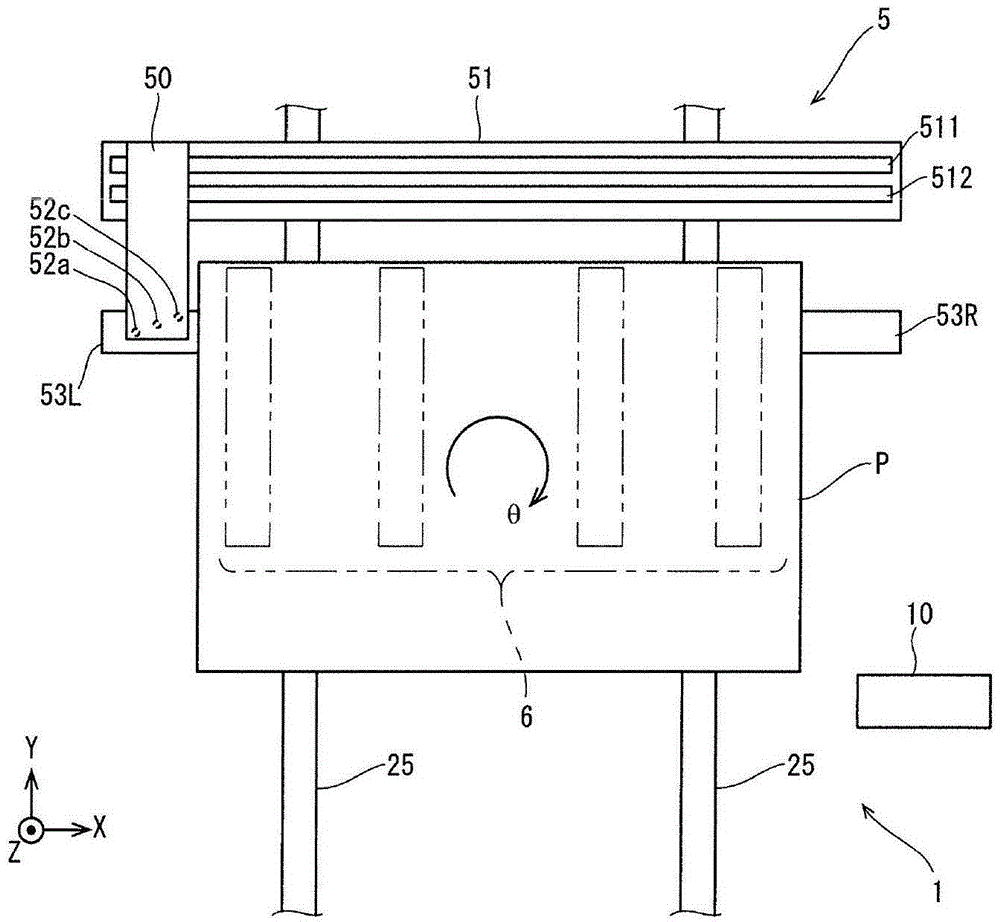
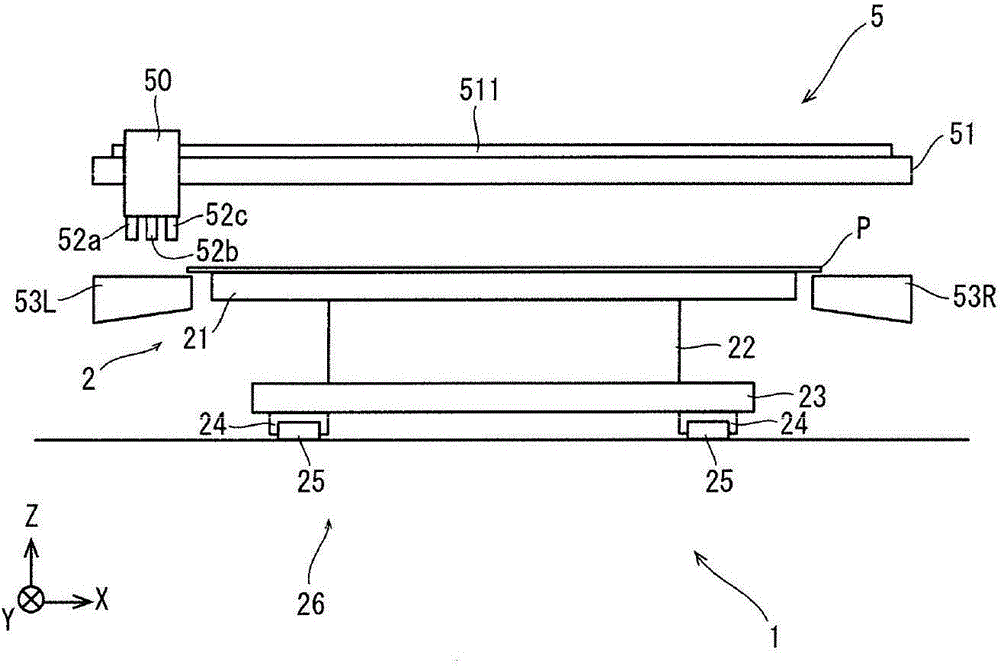
[0126] figure 1 It is a schematic plan view of the coating apparatus 1 of 1st Embodiment. and, figure 2 yes figure 1 A schematic front view of the coating device 1 is shown.

[0127] The coating device 1 is configured as a device for manufacturing an organic EL display device using a fluid material such as an organic EL liquid, a hole transport material, or a hole injection material as a coating liquid. In addition, in the coating device 1, various coating liquids such as an organic EL liquid, a hole transport material, and a hole injection material can be used, but in the following description, the organic EL liquid which is a representative of these coating liquid 3 will be described as a coating solution.

[0128] The coating device 1 includes a substrate holding device 2, an organic EL coating mechanism 5, a mask mechanism 6, and a cleaning mechanism 7 (refer to Figure 7 ) and the control unit 10.

[0129] Such as figure 2 As shown, the substrate holdi...

no. 2 approach >

[0188]

[0189] Figure 13 It is a schematic plan view of 1 A of coating apparatuses of 2nd Embodiment. and, Figure 14 yes Figure 13 A schematic front view of the coating apparatus 1A is shown.

[0190] Also, although not shown, a heating mechanism for preheating the substrate P coated with the organic EL liquid 3 on the surface of the stage 21 is provided inside the stage 21, and the substrate P is adsorbed from below and A suction mechanism for holding, a delivery pin mechanism used for delivering the substrate P between the transfer mechanism, and the like. The stage 21 is a holding portion that holds the substrate P with a flat upper surface. In addition, although the details will be described later, a plurality of magnets 91 are buried inside the platform 21 . The plurality of magnets 91 is an example of a magnetic body that attracts the mask tape 611C to the stage 21 via the substrate P by generating a magnetic field.

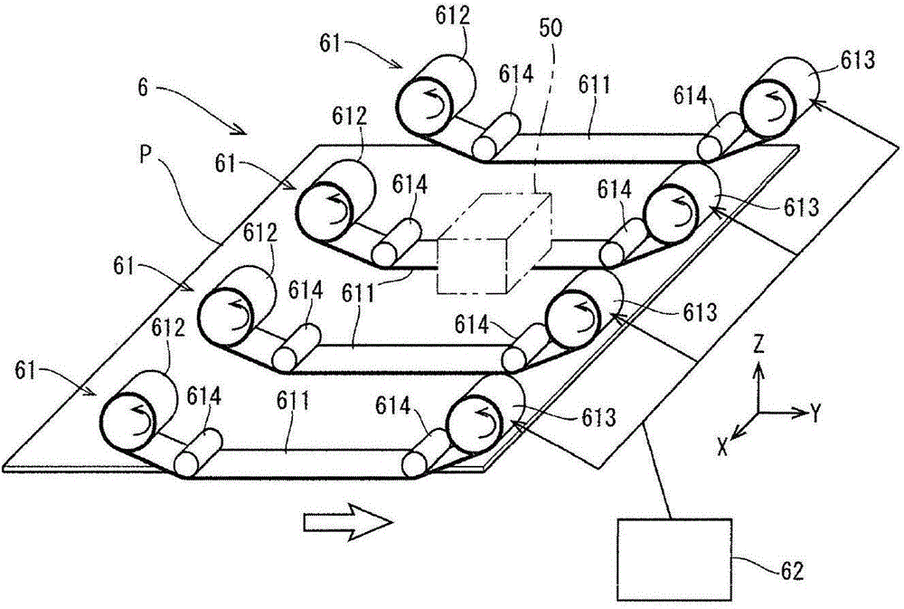
[0191] Figure 15 It is a schematic pers...


PUM


Abstract

The invention provides a coating device and a coating method to enable a non-coated area for a liquid material to be formed on a substrate in an efficient and effective manner. The coating device (1) enables a non-coated area, without coating of an organic electroluminescent liquid (3), on a substrate (P). The coating device (1) comprises a platform (21), a holding substrate (P), a nozzle unit (50) spraying the organic electroluminescent liquid (3) toward the main surface of the substrate (P), a nozzle moving mechanism (51) and a platform moving mechanism (26) that enable the nozzle unit (50) to relatively move in a main scanning direction (X-axis direction) and a subsidiary scanning direction (+Y direction) via the substrate (P) held by the platform (21), and a masking mechanism (6) for providing a masking tape (611) in a way that the portion of the main surface of the substrate (P) is opposite to the corresponding non-coated area and also enabling the masking tape (611) to move along with the movement of the substrate (P).

Description

technical field [0001] The invention relates to a technique for coating a treatment liquid on a substrate. Background technique [0002] In recent years, the development of organic EL display devices utilizing organic electroluminescence (EL) materials has been progressing. For example, in the manufacture of an organic EL display device using an active matrix (active matrix) driving method using a polymer organic EL material, thin film transistors (Thin Film Transistors) are sequentially formed on a glass substrate (hereinafter referred to as "substrate"). , TFT) circuit, forming an indium tin oxide (Indium Tin Oxide, ITO) electrode as an anode, forming a partition wall, and coating a fluid material including a hole (hole) transport material (hereinafter referred to as "hole transport liquid") , forming a hole transport layer by heat treatment, coating a fluid material containing an organic EL material (hereinafter referred to as "organic EL liquid"), forming an organic EL ...

Claims


Application Information

Patent Timeline
IPC IPC(8): B05C5/00B05C11/10
CPCH10K71/00
Inventor 高村幸宏相良秀一铃木聡
Owner DAINIPPON SCREEN MTG CO LTD
Why Eureka
Try Eureka